 مركز مساعدة LTS Connect
Connecting Basics
Typical connection diagrams and port connections for the Sapphire Series CVI DVR, covering video and audio input/output, alarm input/output, relay parameters, and the RS-485 port.
This chapter introduces the typical connection diagrams and ports connections.
Typical Connection Diagram
The following figure is for reference only. The actual product shall govern.
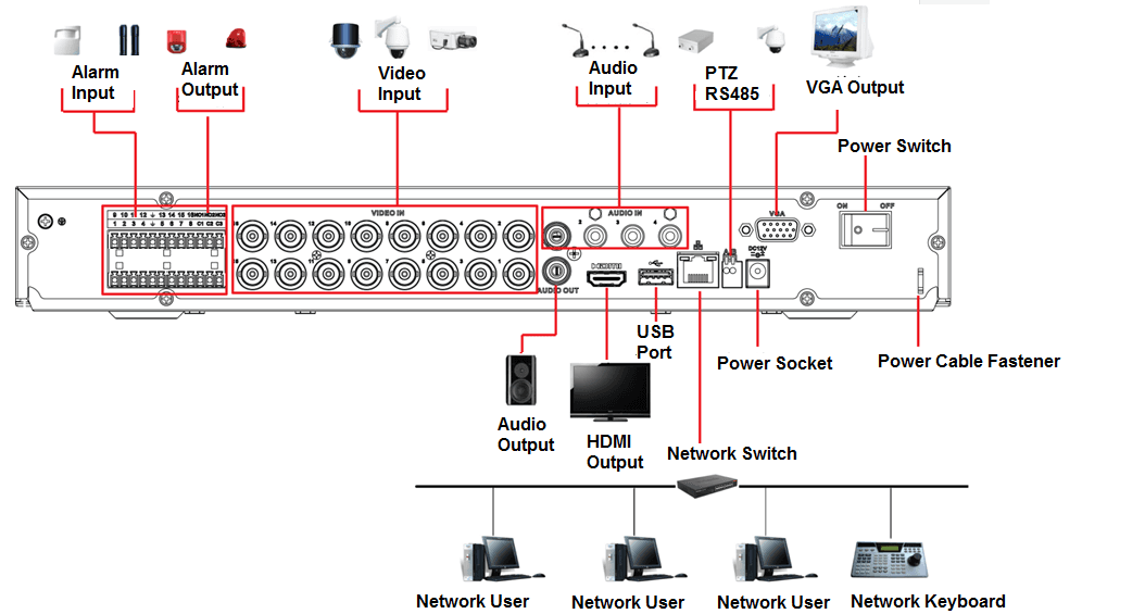
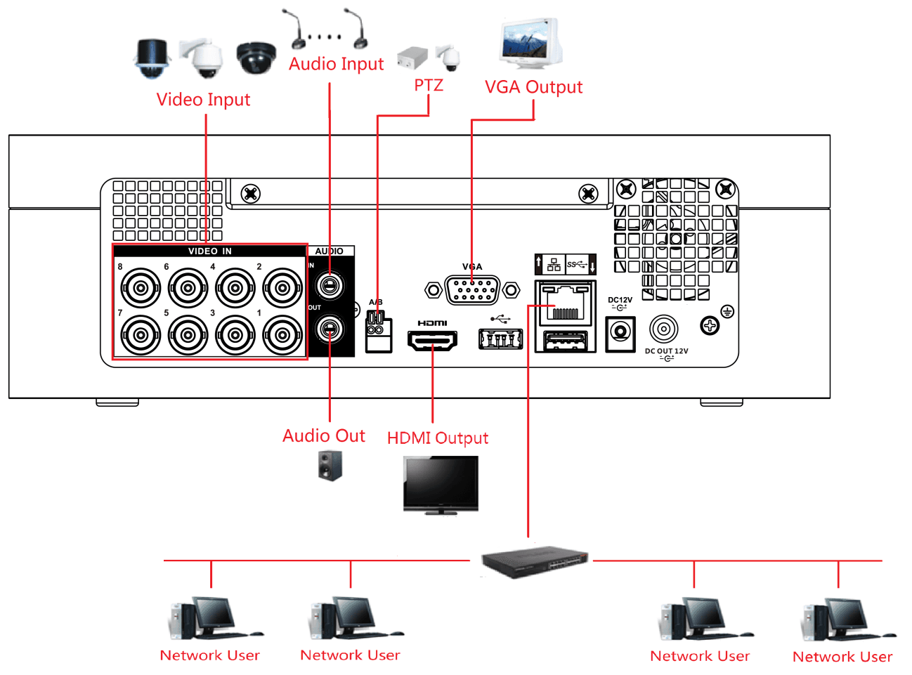
Connecting to Video and Audio Input and Output
Video Input
The video input interface is BNC. The input video format includes: PAL/NTSC BNC (1.0VP-P, 75Ω).
The video signal should comply with your national standards.
The input video signal shall have high SNR, low distortion; low interference, natural color, and suitable lightness.
Guarantee the stability and reliability of the camera signal
The camera shall be installed in a cool, dry place away from the conditions such as direct sunlight, inflammable, and explosive substances.
The camera and the DVR should have the same grounding to ensure the normal operation of the camera.
Guarantee stability and reliability of the transmission line
Please use high quality, sound shielded BNC. Please select suitable BNC model according to the transmission distance.
If the distance is too long, you should use twisted pair cable, and you can add video compensation devices or use optical fiber to ensure video quality.
You should keep the video signal away from the strong electromagnetic interference, especially the high tension current.
Keep connection lugs in well contact
The signal line and shielded wire should be fixed firmly and in well connection. Avoid dry joint, lap welding, and oxidation.
Video Output
Video output includes a BNC (PAL/NTSC1.0VP-P, 75Ω) output, a VGA output, and HDMI output.
System supports BNC, VGA and HDMI output at the same time.
When you are using pc-type monitor to replace the monitor, please pay attention to the following points:
- To defer aging, do not allow the pc monitor to run for a long time.
- Regular demagnetization will keep device maintain proper status.
- Keep it away from strong electromagnetic interference devices.
Using TV as video output device is not a reliable substitution method. You also need to reduce the working hour and control the interference from power supply and other devices. The low quality TV may result in device damage.
Audio Input
This series of products audio input port adopt BNC port.
Due to high impedance of audio input, please use active sound pick-up.
Audio transmission is similar to video transmission. Try to avoid interference, dry joint, loose contact and it shall be away from high tension current.
Audio Output
The audio output signal parameter is usually over 200mv 1KΩ (BNC or RCA). It can directly connect to low impedance earphone, active sound box or amplifier-drive audio output device.
If the sound box and the pick-up cannot be separated spatially, it is easy to arouse squeaking. In this case you can adopt the following measures:
- Use better sound pick-up with better directing property.
- Reduce the volume of the sound box.
- Using more sound-absorbing materials in decoration can reduce voice echo and improve acoustics environment.
- Adjust the layout of speaker and pickup to reduce squeaking.
Connecting to Alarm Input and Output
Please read the followings before connecting.
Alarm input
- Make sure alarm input mode is grounding alarm input.
- Grounding signal is needed for alarm input.
- Alarm input needs the low level voltage signal.
- Alarm input mode can be either NC (Normally Closed) or NO (Normally Open).
- When you are connecting two DVRs or you are connecting one DVR and one other device, use a relay to separate them.
Alarm output
The alarm output port should not be connected to high power load directly (It shall be less than 1A) to avoid high current which might result in relay damage. Use the contactor to realize the connection between the alarm output port and the load.
How to connect PTZ decoder
- Ensure the decoder has the same grounding with DVR; otherwise the PTZ might not be controlled. Shielded twisted wire is recommended and the shielded layer is used to connect to the grounding.
- Avoid high voltage. Ensure proper wiring and some thunder protection measures.
- For too long signal wires, 120Ω should be parallel connected between A, B lines on the far end to reduce reflection and guarantee the signal quality.
- "485 A, B" of DVR cannot parallel connect with "485 port" of other device.
- The voltage between of A, B lines of the decoder should be less than 5V.
Make sure the front-end device has soundly earthed
Improper grounding might result in chip damage.
Introducing Alarm Port
The alarm input ports are dependent on the model you purchased.
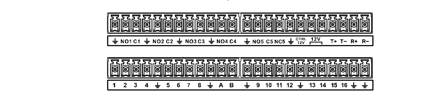
Table 4-1
| Icon | Description |
|---|---|
| 1,2,3,4,5,6,7,8,9,10,11,12,13,14,15,16 | ALARM 1 to ALARM 16. The alarm becomes active in low voltage. |
| NO1 C1, NO2 C2, NO3 C3, NO4 C4 | There are four groups of normally open activation output (on/off button). |
| NO5 C5 NC5, | There is one group of normally open activation output (on/off button). |
| Power output control for alarm (CTRL 12V) | Controls the 6th channel power output for alarm. Electric current: 500mA. When there is an alarm output, close the power output. When the alarm is cancelled, open the power output. |
| +12V | Rated power supply. Electric current: 500mA. |
| Ground cable. | |
| 485 A/B | 485 communication port. They are used to control devices such as decoder. 120Ω should be parallel connected between A, B lines if there are too many PTZ decoders. |
| T+,T-,R+,R- | Four-wire full-duplex RS-485 port. T+ T-: output wire. R+ R-: input wire. |
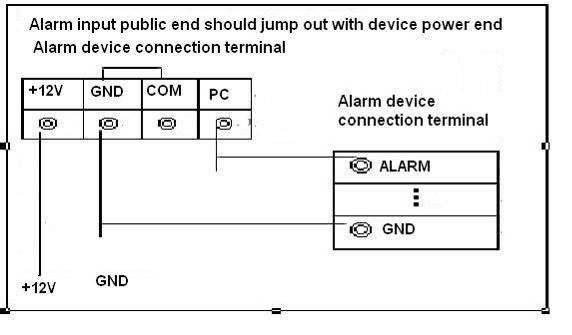
Alarm Input
Refer to the following figure for more information.
- Grounding alarm inputs which includes NO (Normally Open) and NC (Normally Closed) type.
- Parallel connect COM end and GND end of the alarm detector (Provide external power to the alarm detector).
- Parallel connect the Ground of the DVR and the ground of the alarm detector.
- Connect the NC port of the alarm sensor to the DVR alarm input (ALARM).
- Use the same ground with that of DVR if you use external power to the alarm device.
Alarm Output
- Provide external power to external alarm device.
- To avoid overloading, read the following relay parameters table carefully.
- RS-485 A/B cable is for the A/B cable of the PTZ decoder.
Alarm Output Relay Parameters
Refer to the actual product for relay model information.
| Model | HFD23/005-1ZS | HRB1-S-DC5V |
|---|---|---|
| Material of the touch | AgNi+ gold-plating | AuAg10/AgNi10/CuNi30 |
| Rating (Resistance Load) — Rated switch capacity | 30V DC 1A/125V AC 0.5A | 24V DC 1A/125V AC 2A |
| Rating (Resistance Load) — Maximum switch power | 62.5VA/30W | 250VA/48W |
| Rating (Resistance Load) — Maximum switch voltage | 125V AC/60V DC | 125V AC/60V DC |
| Rating (Resistance Load) — Maximum switch currency | 2A | 2A |
| Insulation — Between touches | 400VAC 1 minute | 500VAC 1 minute |
| Insulation — Between touch and winding | 1000VAC 1 minute | 1000VAC 1 minute |
| Turn-on Time | 5ms maximum | 5ms maximum |
| Turn-off Time | 5ms maximum | 5ms maximum |
| Longevity — Mechanical | 1×10⁷ times (300 times/MIN) | 5×10⁶ times (300 times/MIN) |
| Longevity — Electrical | 1×10⁵ times (30 times/MIN) | 2.5×10⁴ times (30 times/MIN) |
| Working Temperature | -30℃—+70℃ | -40℃—+70℃ |
Connecting to RS-485 Port
Connect the RS-485 cable
Connect the RS-485 cable of the PTZ camera to the RS-485 port on the Device. Ensure the match of A and B interfaces.
Connect the video out cable
Connect the video out cable of the PTZ camera to the video input port on the Device.
Turn on the PTZ camera
Turn on the PTZ camera.