 Centrum nápovědy LTS Connect
AI Parameters
Configure the AI parameters of the Sapphire Series NVR, including smart plan, face detection, face recognition, IVS behavior analytics, video structuring, crowd distribution, people counting, heat map, and ANPR.
Smart Plan
The smart plan is for the smart network camera. It includes IVS, human face detection, human face recognition, human body detection, people counting, heat map. If you do not set a rule here, you cannot use these AI intelligent functions when you are connecting to a smart network camera.
This series NVR products support AI by camera only. Make sure the connected network camera supports intelligent functions. For NVR, it just displays the intelligent alarm information from the smart network camera and set or playback the record file.
Open the SMART PLAN interface
Select Main menu > AI > PARAMETERS > SMART PLAN. The SMART PLAN interface is displayed. See the figure below.
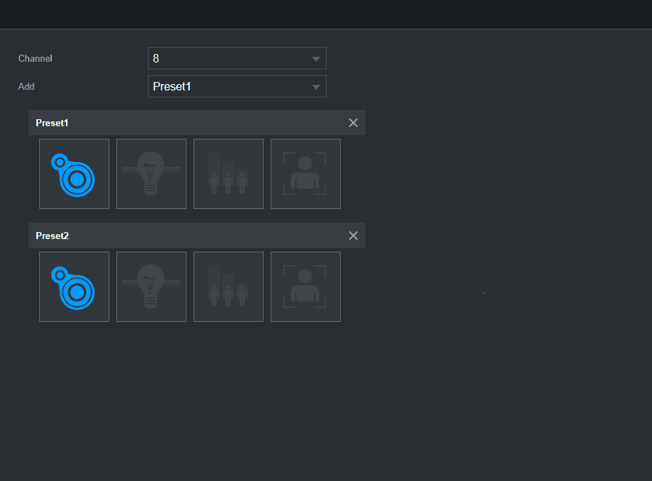
Select a channel number
System displays different smart plan interfaces since the remote device may supports different functions.
The interface is shown as below if the remote device supports preset function.
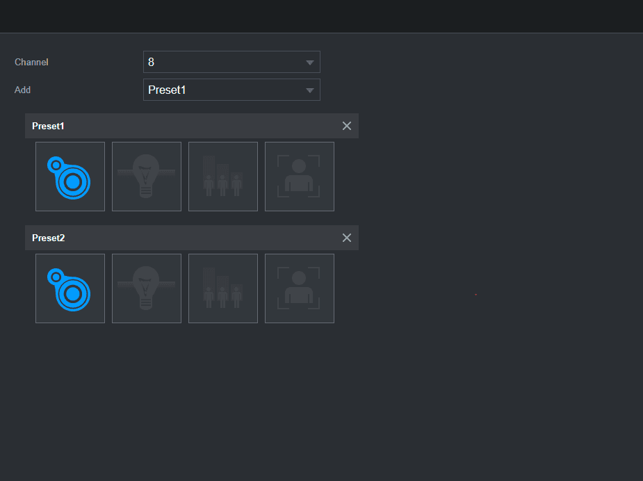
- Select a channel.
- Select a preset.
- Click the smart plan icon at the bottom left. The icon becomes highlighted.
- Click Apply.
- Click the delete icon to delete the preset.
- Click Add to add a preset.
Once the remote device does not support preset function, the interface is shown as below.
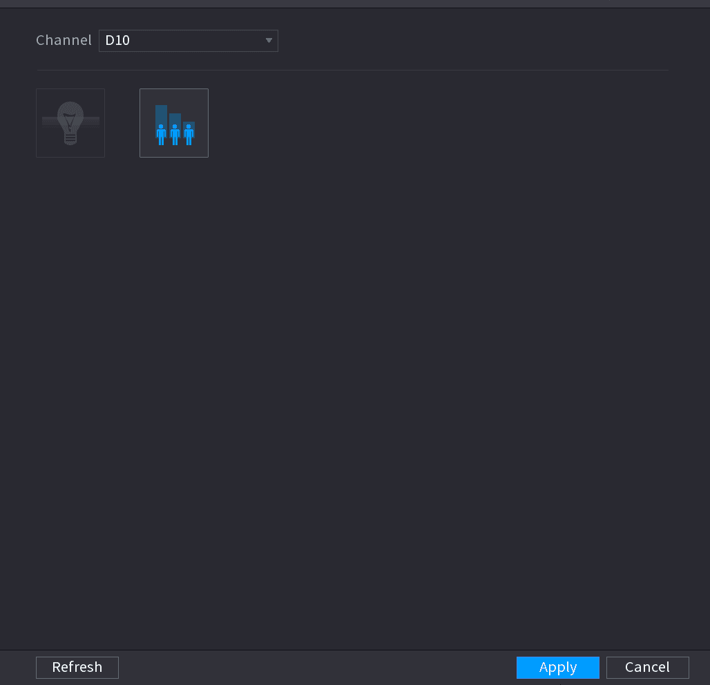
- Select a channel.
- Click the smart plan icon. The icon becomes blue highlighted.
- Click Apply.
Face Detection
The Device can analyze the pictures captured by the camera to detect whether the faces are on the pictures. You can search and filter the recorded videos the faces and play back.
Preparations
The connected camera shall support human face detection function.
Open the FACE DETECTION interface
Select Main Menu > AI > PARAMETERS > FACE DETECTION. The FACE DETECTION interface is displayed. See the figure below.
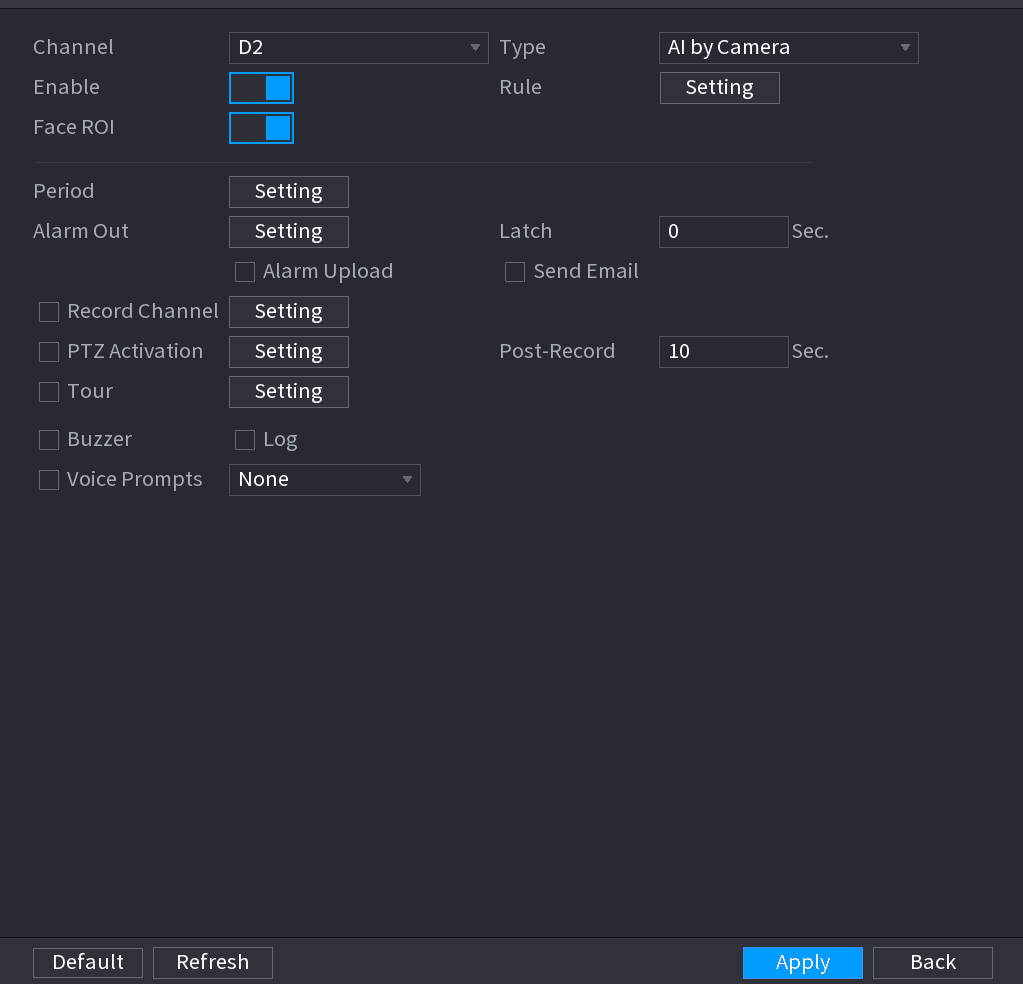
Select and enable a channel
In the Channel list, select a channel that you want to configure face detection function, and then enable it.
Configure the parameters
Configure the parameters. See the table below.
| Parameter | Description |
|---|---|
| Type | This series NVR products support AI by Camera only. AI by Camera means the connected camera does all the AI analytics, and then gives the results to the NVR. |
| Face RoI | Check the box to enable Face RoI function, system displays human face at the enhanced way. |
| Rule | Click Setting to draw areas to filter the target. You can configure two filtering targets (maximum size and minimum size). When the target is smaller than the minimum size or larger than the maximum size, no alarms will be activated. The maximum size should be larger than the minimum size. Left click to drag the four angles to adjust the size. |
| Period | Configure the period and in the set time range, the corresponding configuration item will be linked to start the alarm. |
| Alarm Out | The alarm device (such as lights, sirens, etc.) is connected to the alarm output port. When an alarm occurs, the NVR device transmits the alarm information to the alarm device. |
| Latch | When the alarm ends, the alarm extended for a period of time. The time range is from 0 seconds to 300 seconds. |
| Alarm Upload | Select the check box. When an alarm occurs, the NVR device uploads an alarm signal to the network (including the alarm center). This function is for some series products only. You need to set the alarm center first. For details, see 4.12.9 Alarm Centre. |
| Send Email | Select the check box. When an alarm occurs, the NVR device sends an email to the set mailbox to notify the user. You need to set the email first. For details, see 4.12.6 Email. |
| Record Channel | Select the check box and select the needed recording channel (support multiple choices). When an alarm occurs, the NVR device activates the channel for recording. You need to enable intelligent recording and auto recording first. For details, see 4.1.4.6 Schedule. |
| PTZ Activation | Select the check box and click Setting to select the channel and PTZ action. When an alarm occurs, the NVR device associates the channel to perform the corresponding PTZ action. For example, activate the PTZ in channel one to turn to the preset point X. Tripwire alarm supports to activate PTZ preset point only. You need to set the corresponding PTZ actions first, see 4.4.3 Configuring PTZ Functions. |
| Delay | At the end of the alarm, the recording extends for a period of time. The time range is from 10 seconds to 300 seconds. |
| Tour | Select the check box and select the channel for tour. When an alarm occurs, the local interface of the NVR device displays the selected channel screen. You need to set the time interval and mode for tour first, see 4.16.2 Tour. After the tour is over, the preview interface is restored to the screen split mode before the tour. |
| Log | Select the check box, the NVR device records the alarm information in the log when an alarm occurs. |
| Voice Prompts | Check the box and then select the corresponding audio file from the dropdown list. System plays the audio file when the alarm occurs. Refer to 4.17.1 File Manage to add audio file first. |
| Buzzer | Select the check box to activate the buzzer when an alarm occurs. |
Apply
Click Apply to complete the settings.
Face Recognition
You can compare the detected faces with the faces in the library to judge if the detected face belongs to the library. The comparison result will be displayed on the AI mode live view screen and smart search interface, and link the alarms.
This series NVR products support AI by camera only.
You can use the connected camera to realize AI function. Make sure the connected camera supports human face detection function.
Open the FACE RECOGNITION interface
Select Main Menu > AI > PARAMETERS > FACE RECOGNITION. The FACE RECOGNITION interface is displayed. See the figure below.
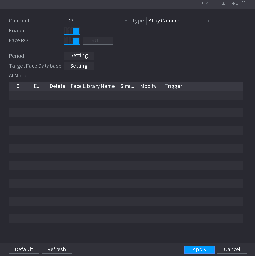
Select and enable a channel
In the Channel list, select a channel that you want to configure face recognition function, and then enable it.
Set the Type
At Type, system supports AI by Camera only.
Set parameters
Set parameters. See the table below.
| Parameter | Description |
|---|---|
| RoI | Check the box to enable RoI function, system displays human face at the enhanced way. |
| Rule | Click Setting to draw areas to filter the target. You can configure two filtering targets (maximum size and minimum size). When the target is smaller than the minimum size or larger than the maximum size, no alarms will be activated. The maximum size should be larger than the minimum size. Left click to drag the four angles to adjust the size. |
| Period | Configure the period and in the set time range, the corresponding configuration item will be linked to start the alarm. |
| Target Face Database | Click Target Face Database, system displays face database list. Select a database from the dropdown list to compare. |
Set the Target Face Database
Set the Target Face Database.
Modify the similarity
(Optional) Click the modify icon to modify the similarity. The lower the number is, the easier the alarm linkage will trigger.
Set the alarm linkage
Click the trigger icon to set the alarm linkage. See the figure below.
Refer to 4.7.3 Database for human target database settings information.
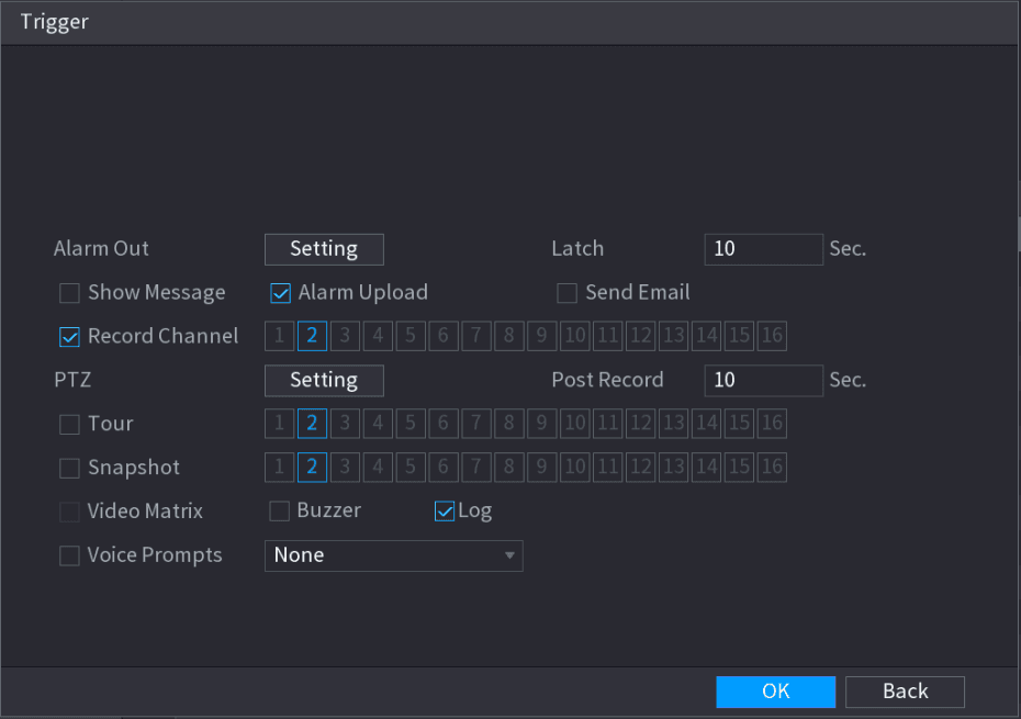
Configure the parameters
Configure the parameters. See the table below.
| Parameter | Description |
|---|---|
| Period | Configure the period and in the set time range, the corresponding configuration item will be linked to start the alarm. |
| Alarm Out | The alarm device (such as lights, sirens, etc.) is connected to the alarm output port. When an alarm occurs, the NVR device transmits the alarm information to the alarm device. |
| Latch | When the alarm ends, the alarm extended for a period of time. The time range is from 0 seconds to 300 seconds. |
| Alarm Upload | Select the check box. When an alarm occurs, the NVR device uploads an alarm signal to the network (including the alarm center). This function is for some series products only. You need to set the alarm center first. For details, see 4.12.9 Alarm Centre. |
| Send Email | Select the check box. When an alarm occurs, the NVR device sends an email to the set mailbox to notify the user. You need to set the email first. For details, see 4.12.6 Email. |
| Record Channel | Select the check box and select the needed recording channel (support multiple choices). When an alarm occurs, the NVR device activates the channel for recording. You need to enable intelligent recording and auto recording first. For details, see 4.1.4.6 Schedule. |
| PTZ Activation | Select the check box and click Setting to select the channel and PTZ action. When an alarm occurs, the NVR device associates the channel to perform the corresponding PTZ action. For example, activate the PTZ in channel one to turn to the preset point X. Tripwire alarm supports to activate PTZ preset point only. You need to set the corresponding PTZ actions first, see 4.4.3 Configuring PTZ Functions. |
| Delay | At the end of the alarm, the recording extends for a period of time. The time range is from 10 seconds to 300 seconds. |
| Tour | Select the check box and select the channel for tour. When an alarm occurs, the local interface of the NVR device displays the selected channel screen. You need to set the time interval and mode for tour first, see 4.16.2 Tour. After the tour is over, the preview interface is restored to the screen split mode before the tour. |
| Log | Select the check box, the NVR device records the alarm information in the log when an alarm occurs. |
| Voice Prompts | Check the box and then select the corresponding audio file from the dropdown list. System plays the audio file when the alarm occurs. Refer to 4.17.1 File Manage to add audio file first. |
| Buzzer | Select the check box to activate the buzzer when an alarm occurs. |
Save the alarm linkage
Click OK, system goes back to human face recognition interface.
Apply
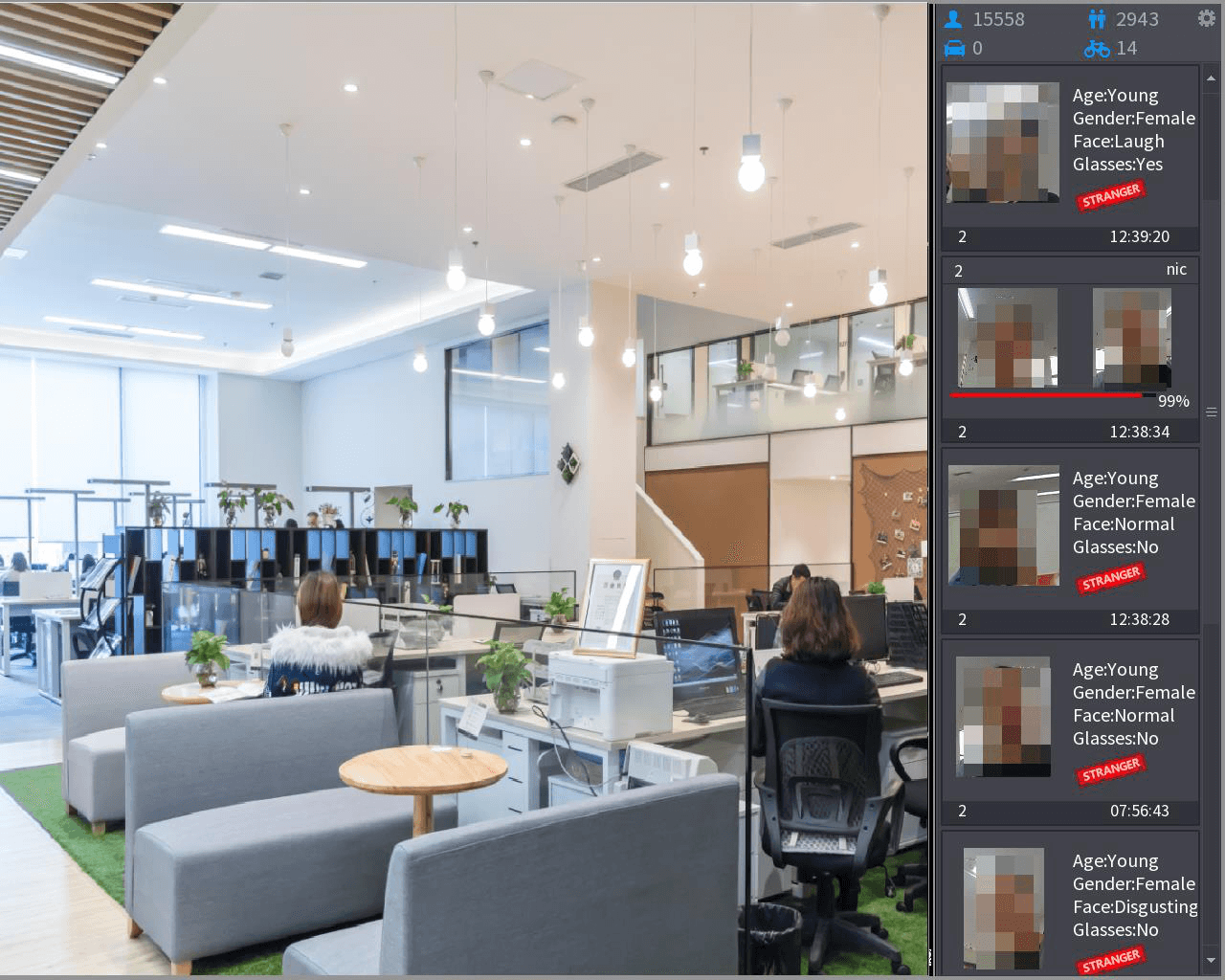
Click Apply to complete the settings. The interface is shown as below if there is matched result.
IVS (General Behavior Analytics)
The IVS function processes and analyzes the images to extract the key information to match with the specified rules. When the detected behaviors match with the rules, the system activates alarms.
- This function is for some series product only.
- IVS function and human face detection function cannot be valid at the same time.
The IVS function environment shall meet the following requirements:
- The object total size shall not be more than 10% of the whole video.
- The object size on the video shall not be more than 10pixels10 pixels. The abandoned object size shall be more than 15pixels15 pixels (CIF resolution). The object width shall not be more than 1/3 of the video height and width. The recommended height is 10% of the video.
- The object and the background brightness different shall be more than 10 grey levels.
- The object shall remain on the video for more than 2 seconds. The moving distance is larger than its own width and shall not be smaller than 15pixels (CIF resolution).
- The surveillance environment shall not be too complicated. The IVS function is not suitable for the environment of too many objects or the changing light.
- The surveillance environment shall not contain glasses, reflection light from the ground, and water. Free of tree branches, shadow, mosquito and bugs. Do not use the IVS function in the backlight environment, avoid direct sunlight.
Open the IVS interface
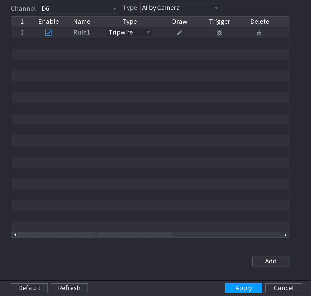
Select Main Menu > AI > PARAMETERS > IVS. The IVS interface is displayed. See the figure below.
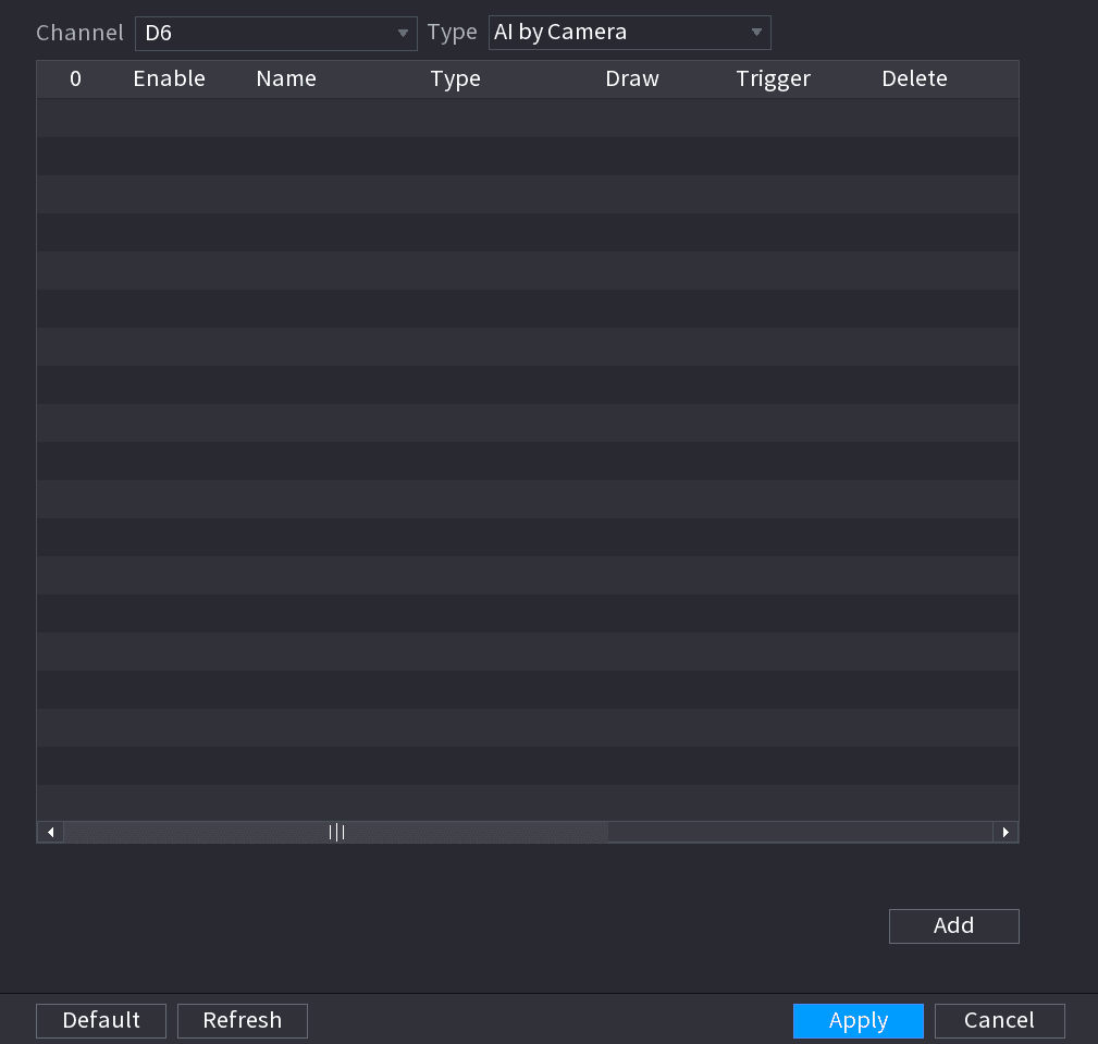
Add a rule
Select a channel from the dropdown list. Click Add and then set corresponding rule. See the figure below.
Click the delete icon to delete the selected rule.
Set parameters
Set corresponding parameters.
Apply
Click Apply.
Tripwire
When the detection target crosses the warning line along the set direction, the system performs an alarm linkage action.
Select Tripwire
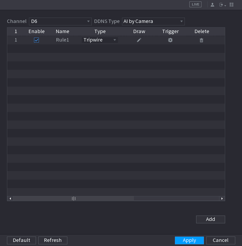
Select Main Menu > AI > PARAMETERS > IVS. In the Type drop-down list, select Tripwire. See the figure below.
Draw the detection rule
- Click the draw icon to draw the rule on the surveillance video, the system displays as below.
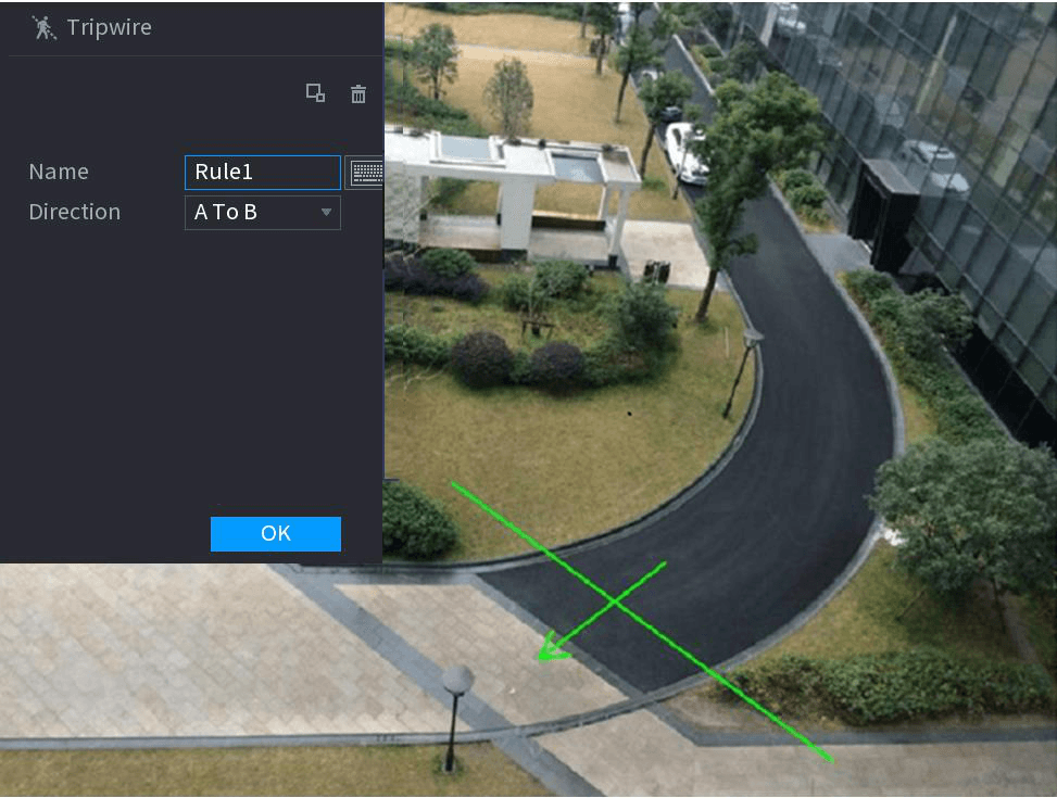
- Configure the parameters. See the table below.
| Parameter | Description |
|---|---|
| Name | Customize the rule name. |
| Direction | Set the tripwire direction, including A→B, B→A and A↔B. |
| Filter target | Click the filter icon to filter the target. Check the blue wireframe and adjust the size of the area with the mouse. Each rule can set 2 target filters (maximum size and minimum size), that is, when the passing target is smaller than the minimum target or larger than the maximum target, no alarm will be generated. The maximum size should not be smaller than the minimum size. |
| AI Recognition | Select AI recognition and the system displays alarm target. The default selection is person and motor vehicle and system automatically identifies the person and motor vehicle appeared within the monitoring range. When you select IVS of AI by camera, the connected channel shall support tripwire function. |
- Press and hold down the left button on the monitor screen to draw the line. The line can be a straight line or a curve.
- Click OK to complete the rule setting.
Open the Trigger interface
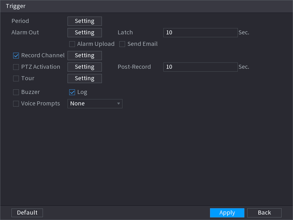
Click the trigger icon. System displays the Trigger interface. See the figure below.
Configure the parameters
Configure the parameters. See the table below.
| Parameter | Description |
|---|---|
| Period | Configure the period and in the set time range, the corresponding configuration item will be linked to start the alarm. |
| Alarm Out | The alarm device (such as lights, sirens, etc.) is connected to the alarm output port. When an alarm occurs, the NVR device transmits the alarm information to the alarm device. |
| Latch | When the alarm ends, the alarm extended for a period of time. The time range is from 0 seconds to 300 seconds. |
| Alarm Upload | Select the check box. When an alarm occurs, the NVR device uploads an alarm signal to the network (including the alarm center). This function is for some series products only. You need to set the alarm center first. For details, see 4.12.9 Alarm Centre. |
| Send Email | Select the check box. When an alarm occurs, the NVR device sends an email to the set mailbox to notify the user. You need to set the email first. For details, see 4.12.6 Email. |
| Record Channel | Select the check box and select the needed recording channel (support multiple choices). When an alarm occurs, the NVR device activates the channel for recording. You need to enable intelligent recording and auto recording first. For details, see 4.1.4.6 Schedule. |
| PTZ Activation | Select the check box and click Setting to select the channel and PTZ action. When an alarm occurs, the NVR device associates the channel to perform the corresponding PTZ action. For example, activate the PTZ in channel one to turn to the preset point X. Tripwire alarm supports to activate PTZ preset point only. You need to set the corresponding PTZ actions first, see 4.4.3 Configuring PTZ Functions. |
| Delay | At the end of the alarm, the recording extends for a period of time. The time range is from 10 seconds to 300 seconds. |
| Tour | Select the check box and select the channel for tour. When an alarm occurs, the local interface of the NVR device displays the selected channel screen. You need to set the time interval and mode for tour first, see 4.16.2 Tour. After the tour is over, the preview interface is restored to the screen split mode before the tour. |
| Log | Select the check box, the NVR device records the alarm information in the log when an alarm occurs. |
| Voice Prompts | Check the box and then select the corresponding audio file from the dropdown list. System plays the audio file when the alarm occurs. Refer to 4.17.1 File Manage to add audio file first. |
| Buzzer | Select the check box to activate the buzzer when an alarm occurs. |
Save the alarm setting
Click OK to save the alarm setting. System displays the IVS interface.
Apply
Select the Enable check box and click Apply to complete the tripwire setting.
Intrusion
When the detection target passes the edge of the monitoring area, and enters, leaves or traverses the monitoring area, the system performs an alarm linkage action.
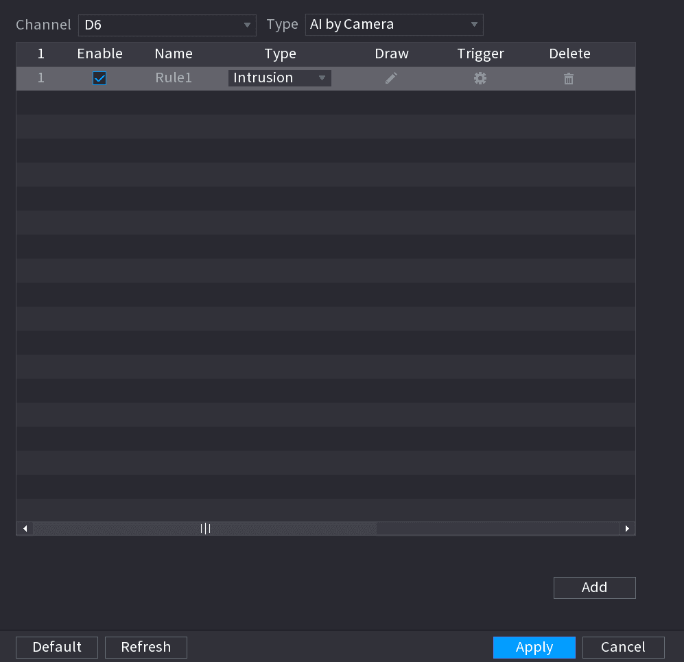
Draw the detection rule
- Click the draw icon to draw the rule on the surveillance video, the system displays as below.
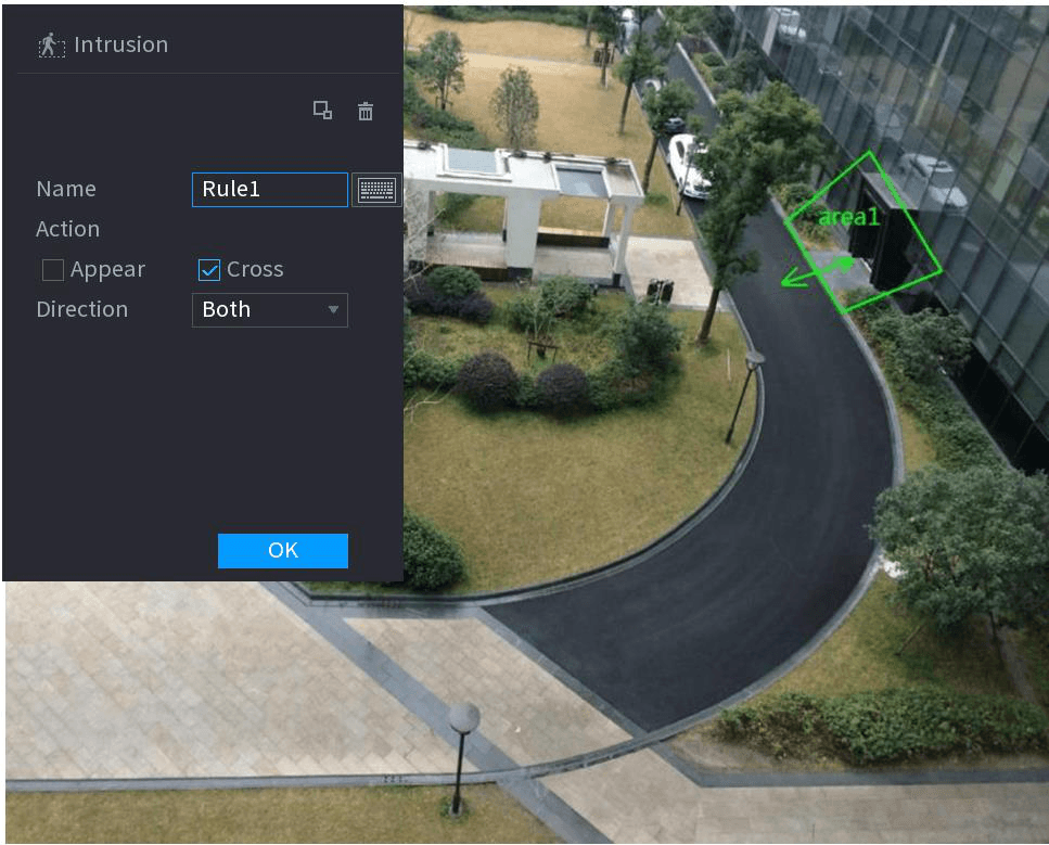
- Configure the parameters. See the table below.
| Parameter | Description |
|---|---|
| Name | Customize the rule name. |
| Action | Set the intrusion action, including appear and crossing area. |
| Direction | Set the direction to cross the area, including enter, exit and both. |
| Filter target | Click the filter icon to filter the target. Check the blue wireframe and adjust the size of the area with the mouse. Each rule can set 2 target filters (maximum size and minimum size), that is, when the passing target is smaller than the minimum target or larger than the maximum target, no alarm will be generated. The maximum size should not be smaller than the minimum size. |
| AI recognition | Select AI recognition and the system displays alarm target. The default selection is person and motor vehicle and system automatically identifies the person and motor vehicle appeared within the monitoring range. |
- Press and hold down the left button on the monitoring screen to draw the monitoring area.
- Click OK to complete the rule setting.
Set the alarm linkage
Click the trigger icon, you can refer to the Tripwire section to set other parameters.
Apply
Select the Enable check box and click Apply to complete the intrusion setting.
Abandoned Object Detection
System generates an alarm when there is abandoned object in the specified zone.
Select Abandoned Object
In the Type drop-down list, select Abandoned Object. The interface is shown as below.
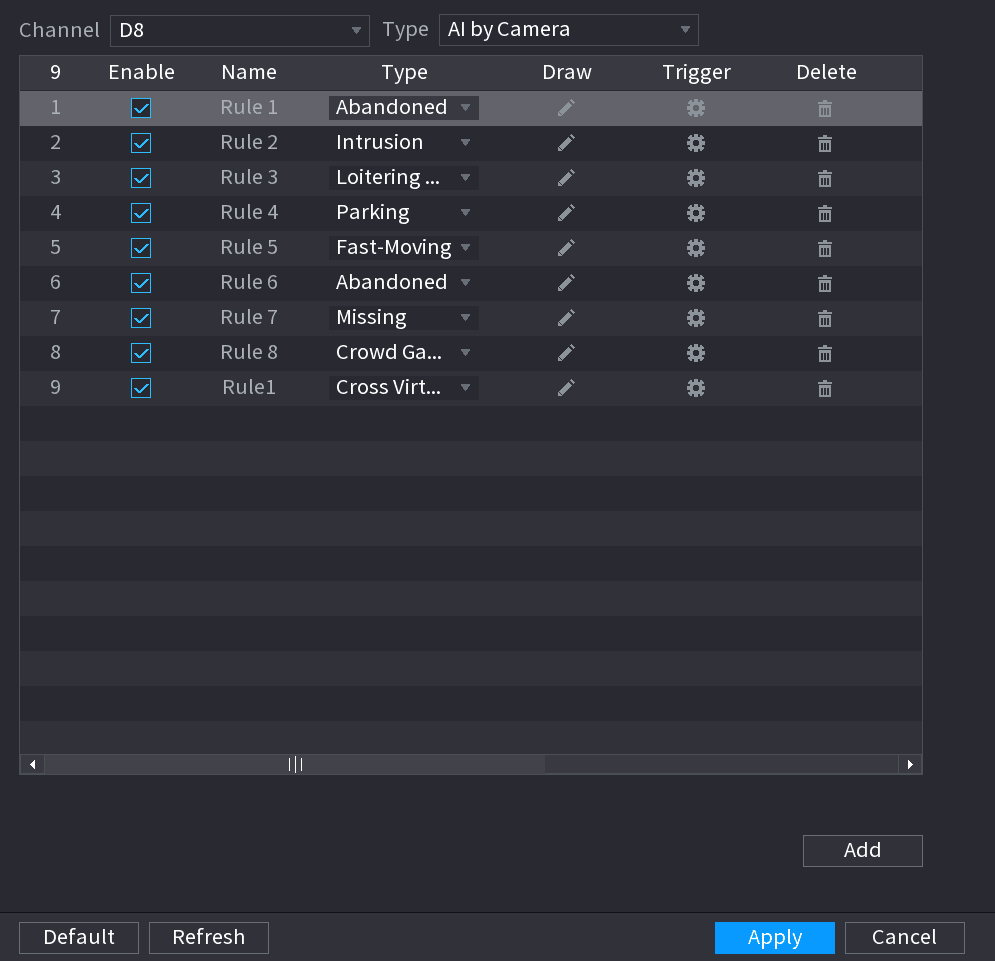
Draw the detection rule
- Click the draw icon to draw the rule on the surveillance video. See the figure below.
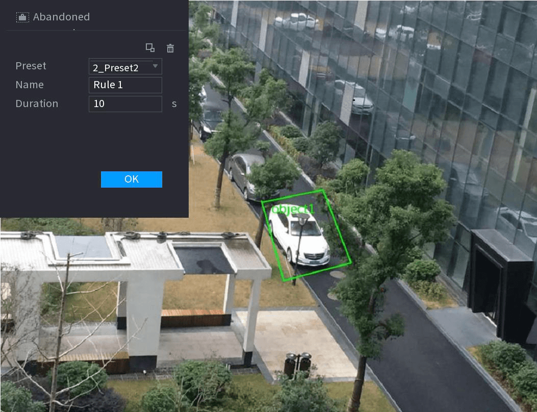
- Set parameters. See the table below.
| Parameter | Description |
|---|---|
| Preset | Select a preset you want to use IVS |
| Name | Input customized rule name |
| Duration | System can generate an alarm once the object is in the zone for the specified period. |
| Filter target | Click the filter icon to filter the target. Check the blue wireframe and adjust the size of the area with the mouse. Each rule can set 2 target filters (maximum size and minimum size), that is, when the passing target is smaller than the minimum target or larger than the maximum target, no alarm will be generated. The maximum size should not be smaller than the minimum size. |
- Draw a rule. Left click mouse to draw a zone, until you draw a rectangle, you can right click mouse.
- Click OK to complete the rule setting.
Set the alarm linkage
Click the trigger icon, you can refer to the Tripwire section to set other parameters.
Apply
Click Apply to complete the setup.
Fast moving
You can detect the fast moving object in the specified zone.
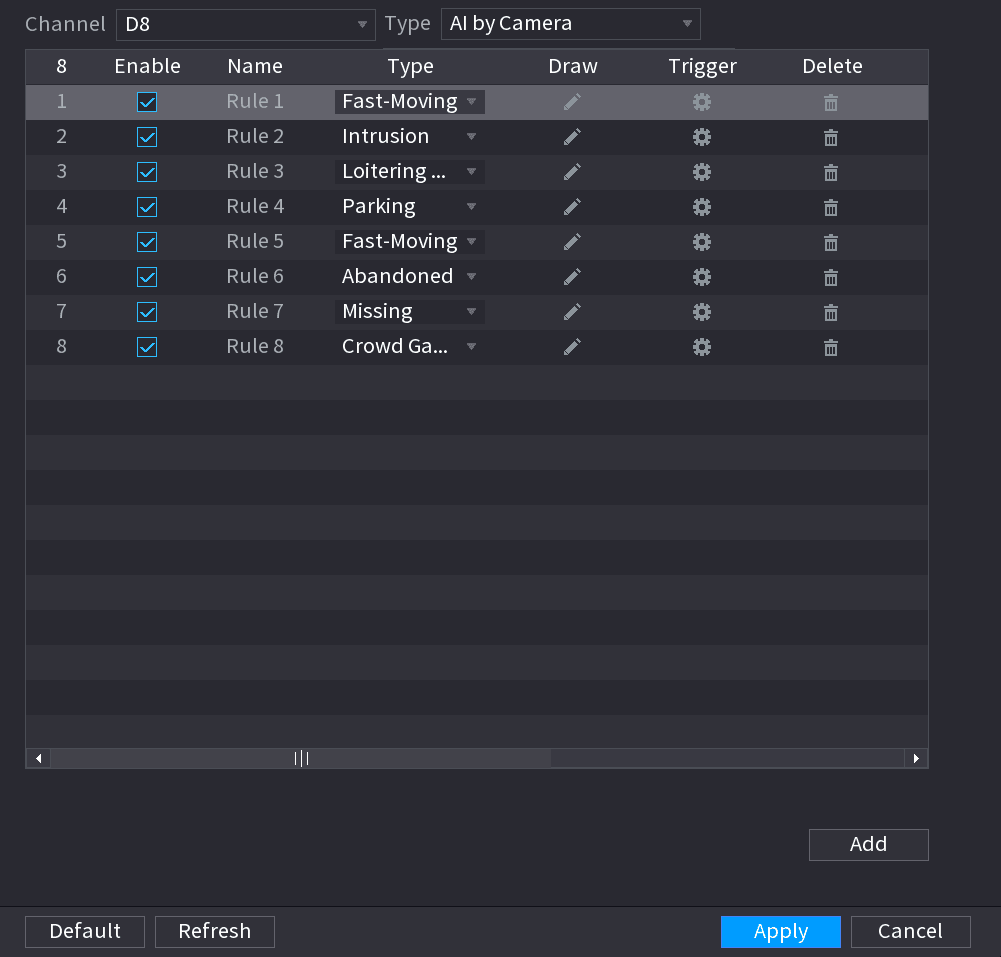
Draw the detection rule
- Click the draw icon to draw the rule on the surveillance video. See the figure below.
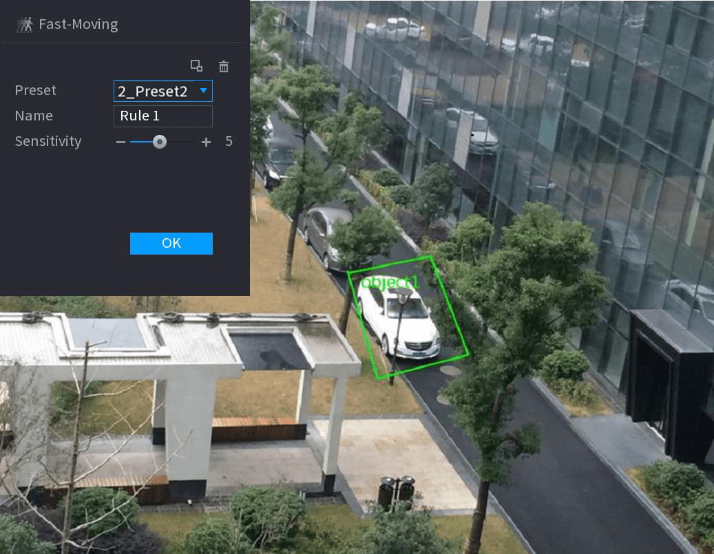
- Set parameters. See the table below.
| Parameter | Description |
|---|---|
| Preset | Select a preset you want to use IVS |
| Name | Input customized rule name |
| Sensitivity | You can set alarm sensitivity. The value ranges from 1 to 10. The default setup is 5. |
| Filter target | Click the filter icon to filter the target. Check the blue wireframe and adjust the size of the area with the mouse. Each rule can set 2 target filters (maximum size and minimum size), that is, when the passing target is smaller than the minimum target or larger than the maximum target, no alarm will be generated. The maximum size should not be smaller than the minimum size. |
- Draw a rule. Left click mouse to draw a zone, until you draw a rectangle, you can right click mouse.
- Click OK to complete the rule setting.
Set the alarm linkage
Click the trigger icon, you can refer to the Tripwire section to set other parameters.
Apply
Click Apply to complete the setup.
Crowd Gathering
System can generate an alarm once the people amount gathering in the specified zone is larger than the threshold.
Select Crowd Gathering Estimation
In the Type drop-down list, select Crowd Gathering Estimation. The interface is shown as below.
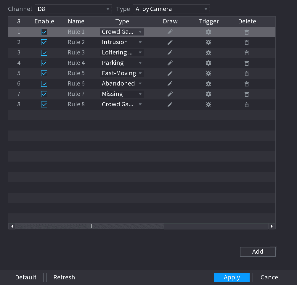
Draw the detection rule
- Click the draw icon to draw the rule on the surveillance video. See the figure below.
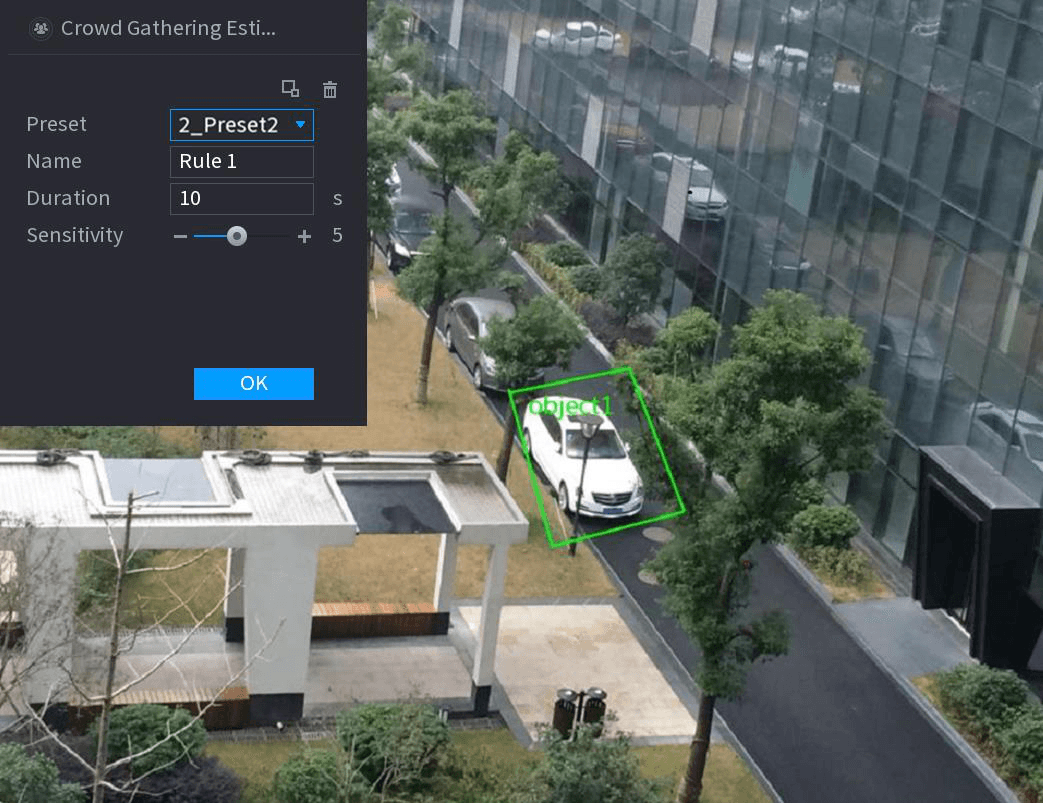
- Set parameters. See the table below.
| Parameter | Description |
|---|---|
| Preset | Select a preset you want to use IVS. |
| Name | Input customized rule name |
| Duration | Set the minimum time that the object stays until the alarm is triggered. |
| Filter target | Click the filter icon to filter the target. Check the blue wireframe and adjust the size of the area with the mouse. Each rule can set 2 target filters (maximum size and minimum size), that is, when the passing target is smaller than the minimum target or larger than the maximum target, no alarm will be generated. The maximum size should not be smaller than the minimum size. |
- Draw a rule. Left click mouse to draw a zone, until you draw a rectangle, you can right click mouse.
- Click OK to complete the rule setting.
Set the alarm linkage
Click the trigger icon, you can refer to the Tripwire section to set other parameters.
Apply
Click Apply to complete the setup.
Parking
When the detection target stays in the monitoring area for more than the set duration, the system performs alarm linkage action.
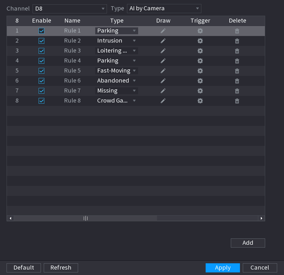
Draw the detection rule
- Click the draw icon to draw the rule on the surveillance video. See the figure below.
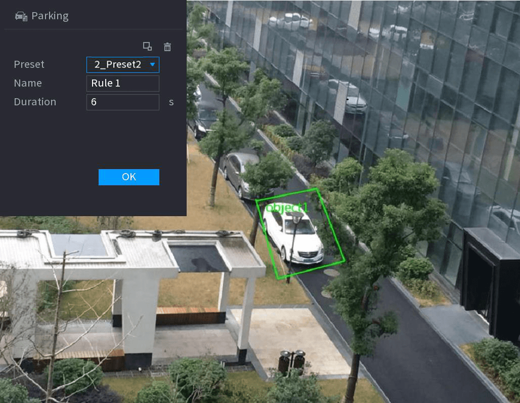
- Set parameters. See the table below.
| Parameter | Description |
|---|---|
| Preset | Set the preset point for IVS detection according to the actual needs. |
| Name | Customize the rule name. |
| Duration | Set the minimum time that the object stays until the alarm is triggered. |
| Filter target | Click the filter icon to filter the target. Check the blue wireframe and adjust the size of the area with the mouse. Each rule can set 2 target filters (maximum size and minimum size), that is, when the passing target is smaller than the minimum target or larger than the maximum target, no alarm will be generated. The maximum size should not be smaller than the minimum size. |
- Draw a rule. Left click mouse to draw a zone, until you draw a rectangle, you can right click mouse.
- Click OK to complete the rule setting.
Set the alarm linkage
Click the trigger icon, you can refer to the Tripwire section to set other parameters.
Apply
Click Apply to complete the setup.
Missing Object Detection
System generates an alarm when there is missing object in the specified zone.
Select Missing Object
In the Type drop-down list, select Missing Object. The interface is shown as below.
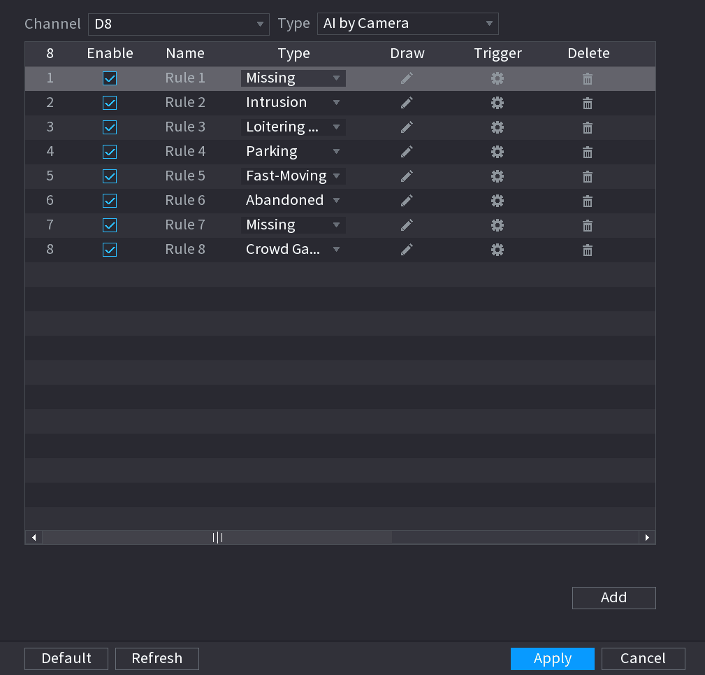
Draw the detection rule
- Click the draw icon to draw the rule on the surveillance video. See the figure below.
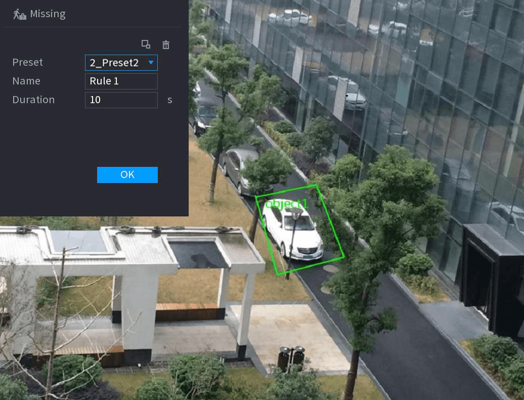
- Set parameters. See the table below.
| Parameter | Description |
|---|---|
| Preset | Set the preset point for IVS detection according to the actual needs. |
| Name | Customize the rule name. |
| Duration | Set the minimum time that the object stays until the alarm is triggered. |
| Filter target | Click the filter icon to filter the target. Check the blue wireframe and adjust the size of the area with the mouse. Each rule can set 2 target filters (maximum size and minimum size), that is, when the passing target is smaller than the minimum target or larger than the maximum target, no alarm will be generated. The maximum size should not be smaller than the minimum size. |
- Draw a rule. Left click mouse to draw a zone, until you draw a rectangle, you can right click mouse.
- Click OK to complete the rule setting.
Set the alarm linkage
Click the trigger icon, you can refer to the Tripwire section to set other parameters.
Apply
Click Apply to complete the setup.
Loitering Detection
System can generate an alarm once the object is staying in the specified zone longer than the threshold.
Select Loitering Detection
In the Type drop-down list, select Loitering Detection. The interface is shown as below.
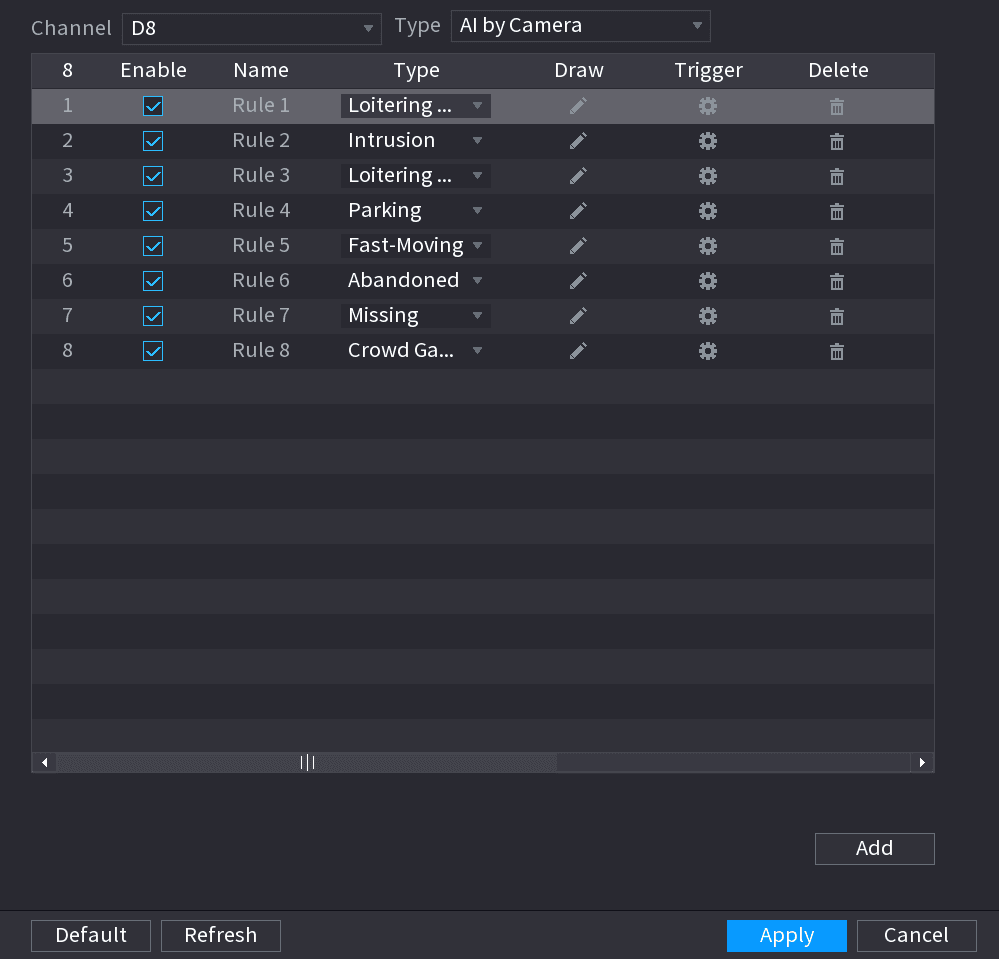
Draw the detection rule
- Click the draw icon to draw the rule on the surveillance video. See the figure below.
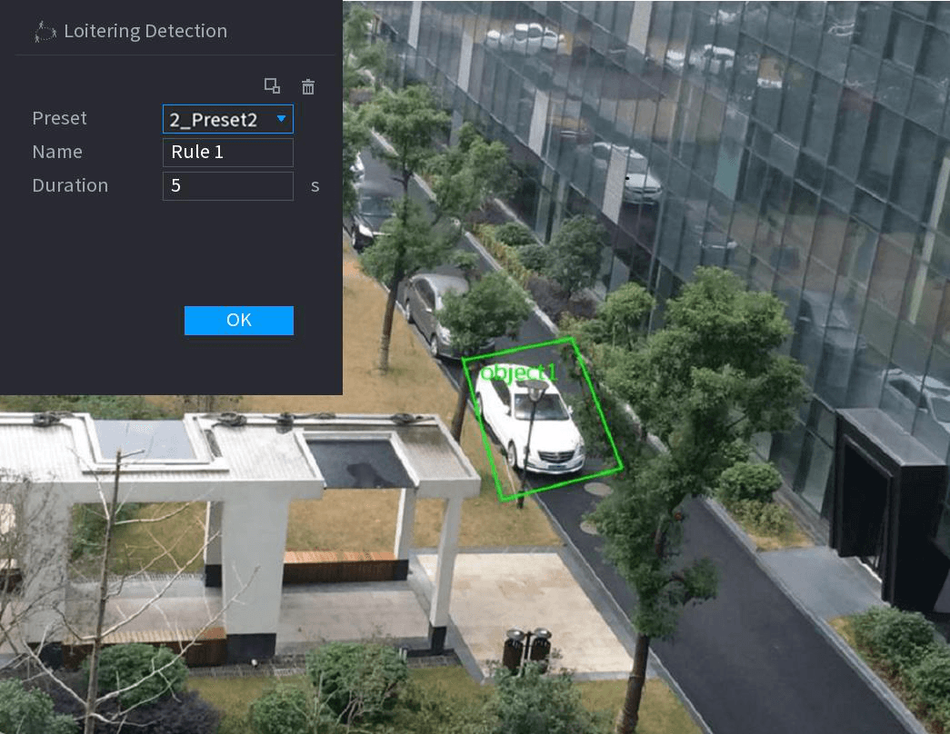
- Set parameters. See the table below.
| Parameter | Description |
|---|---|
| Preset | Set the preset point for IVS detection according to the actual needs. |
| Name | Customize the rule name. |
| Duration | Set the minimum time that the object stays until the alarm is triggered. |
| Filter target | Click the filter icon to filter the target. Check the blue wireframe and adjust the size of the area with the mouse. Each rule can set 2 target filters (maximum size and minimum size), that is, when the passing target is smaller than the minimum target or larger than the maximum target, no alarm will be generated. The maximum size should not be smaller than the minimum size. |
- Draw a rule. Left click mouse to draw a zone, until you draw a rectangle, you can right click mouse.
- Click OK to complete the rule setting.
Set the alarm linkage
Click the trigger icon, you can refer to the Tripwire section to set other parameters.
Apply
Click Apply to complete the setup.
Video Structuring (Metadata)
The device can detect and extract key features from the human body, motor vehicle, and non-motor vehicles in the video, and then build a structured database. You can search any target you need with these features.
After enable the video structuring function, the corresponding smart plan can become valid.
Preparations
Make sure the connected camera supports video structuring (metadata) function.
Open the VIDEO STRUCTURING interface
Select Main Menu > AI > PARAMETERS > VIDEO STRUCTURING. The VIDEO STRUCTURING interface is displayed. See the figure below.
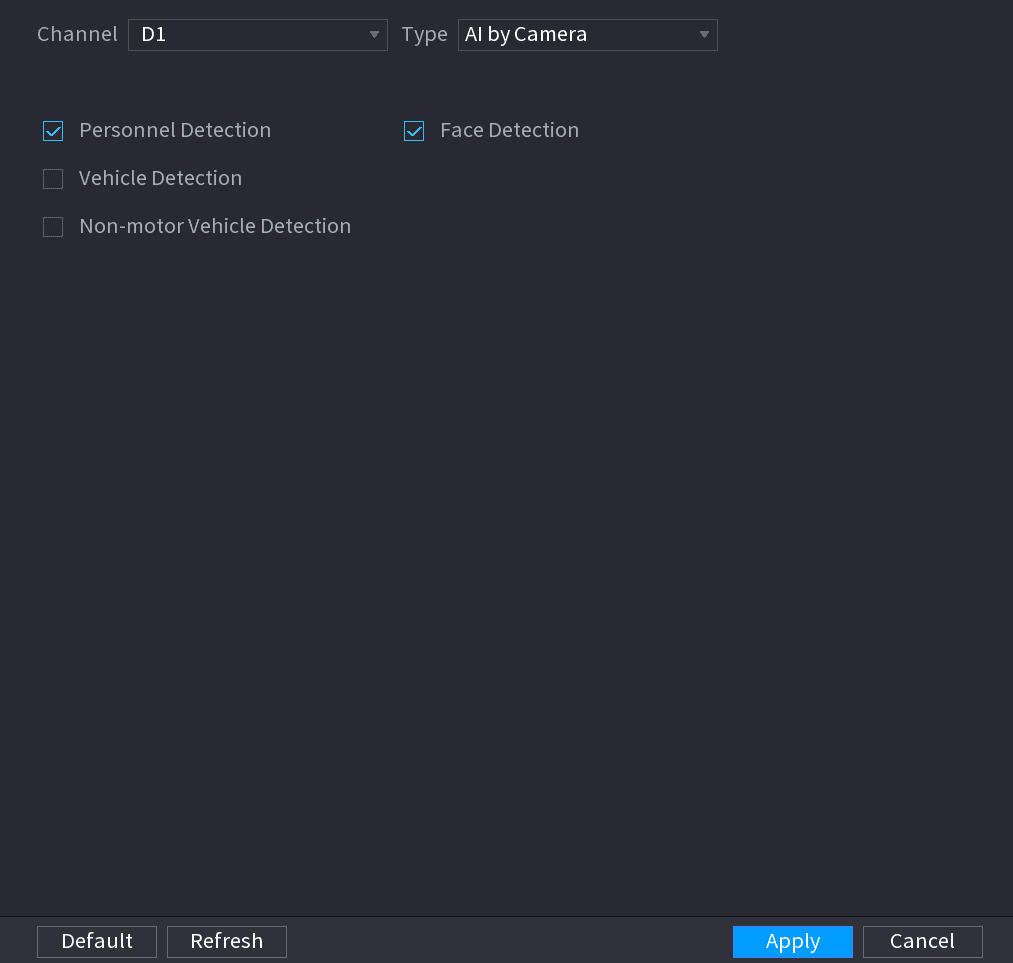
Select and enable a channel
In the Channel list, select a channel that you want to configure video structuring function, and then enable it. See the table below.
| Parameter | Description |
|---|---|
| Human Detection | Select Human detection and then check the box to enable this function. |
| Face Detect | Select Face Detect and then check the box to enable this function. |
| Vehicle detection | Select Vehicle detection and then check the box to enable this function. |
| Non-motor Vehicle | Select Non-motor Vehicle and then check the box to enable this function. |
Apply
Click Apply.
Crowd Distribution
Connecting to the front-end device that supports crowd distribution function, system can support the crowd distribution function. It supports crowd distribution event subscription and receive. It supports crowd distribution global and regional density settings, linkage alarm and triggered video storage, or upload the data to the platform. After connecting to the general network camera, the system adopts the algorithm to analyze the crowd density and trigger the corresponding actions.
Open the CROWD DISTRIBUTION interface
Select Main Menu > AI > PARAMETERS > CROWD DISTRIBUTION. The CROWD DISTRIBUTION interface is displayed. See the figure below.
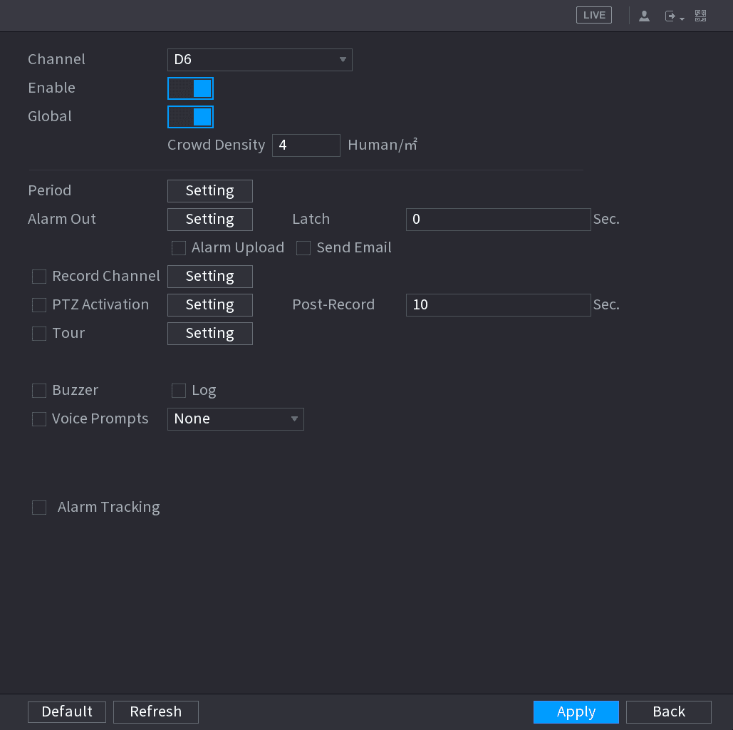
Configure parameters
Configure parameters. See the table below.
| Parameter | Description |
|---|---|
| Channel | Select a channel from the dropdown list. |
| Enable | Check the box to enable the function. |
| Global | Check the box to enable global crowd distribution alarm. |
| Crowd Density | Configure the alarm threshold. The default setup is 4 persons/㎡. The value ranges from 2 to 10. |
| Period | Configure the period and in the set time range, the corresponding configuration item will be linked to start the alarm. |
| Alarm Out | The alarm device (such as lights, sirens, etc.) is connected to the alarm output port. When an alarm occurs, the NVR device transmits the alarm information to the alarm device. |
| Latch | When the alarm ends, the alarm extended for a period of time. The time range is from 0 seconds to 300 seconds. |
| Alarm Upload | Select the check box. When an alarm occurs, the NVR device uploads an alarm signal to the network (including the alarm center). This function is for some series products only. You need to set the alarm center first. For details, see 4.12.9 Alarm Centre. |
| Send Email | Select the check box. When an alarm occurs, the NVR device sends an email to the set mailbox to notify the user. You need to set the email first. For details, see 4.12.6 Email. |
| Record Channel | Select the check box and select the needed recording channel (support multiple choices). When an alarm occurs, the NVR device activates the channel for recording. You need to enable intelligent recording and auto recording first. For details, see 4.1.4.6 Schedule. |
| PTZ Activation | Select the check box and click Setting to select the channel and PTZ action. When an alarm occurs, the NVR device associates the channel to perform the corresponding PTZ action. For example, activate the PTZ in channel one to turn to the preset point X. Tripwire alarm supports to activate PTZ preset point only. You need to set the corresponding PTZ actions first, see 4.4.3 Configuring PTZ Functions. |
| Delay | At the end of the alarm, the recording extends for a period of time. The time range is from 10 seconds to 300 seconds. |
| Tour | Select the check box and select the channel for tour. When an alarm occurs, the local interface of the NVR device displays the selected channel screen. You need to set the time interval and mode for tour first, see 4.16.2 Tour. After the tour is over, the preview interface is restored to the screen split mode before the tour. |
| Log | Select the check box, the NVR device records the alarm information in the log when an alarm occurs. |
| Voice Prompts | Check the box and then select the corresponding audio file from the dropdown list. System plays the audio file when the alarm occurs. Refer to 4.17.1 File Manage to add audio file first. |
| Buzzer | Select the check box to activate the buzzer when an alarm occurs. |
Apply
Click Apply to complete the setup.
People Counting
System adopts video image and graphics analysis technology. System can calculate the entry/exit people amount in the specified zone on the video. It can generate an alarm when the amount has exceeded the threshold.
People Counting
Open the PEOPLE COUNTING interface
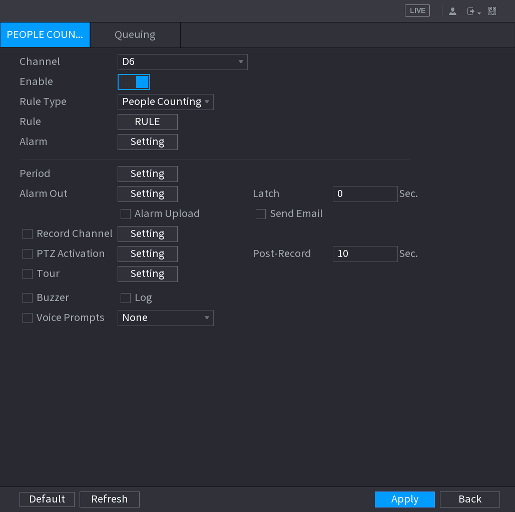
Select Main Menu > AI > PARAMETERS > PEOPLE COUNTING > PEOPLE COUNTING. The PEOPLE COUNTING interface is displayed. See the figure below.
Configure parameters
Configure parameters. See the table below.
| Parameter | Description |
|---|---|
| Channel | Select a channel from the dropdown list. |
| Enable | Check the box to enable the function. |
| Rule Type | Select a people counting rule type. |
| Rule | Click RULE to set statistics region, name, direction. |
| Alarm | Click Setting to set alarm parameters. ⚫ OSD Overlay: Check the box here; you can view the people amount on the surveillance video. ⚫ Entry No.: You can set people entry amount. System can generate an alarm once the amount has exceeded the threshold. ⚫ Exit No.: You can set people exit amount. System can generate an alarm once the amount has exceeded the threshold. ⚫ Remaining No.: You can set people staying amount in the zone. System can generate an alarm once the amount has exceeded the threshold. |
| Period | Configure the period and in the set time range, the corresponding configuration item will be linked to start the alarm. |
| Alarm Out | The alarm device (such as lights, sirens, etc.) is connected to the alarm output port. When an alarm occurs, the NVR device transmits the alarm information to the alarm device. |
| Latch | When the alarm ends, the alarm extended for a period of time. The time range is from 0 seconds to 300 seconds. |
| Alarm Upload | Select the check box. When an alarm occurs, the NVR device uploads an alarm signal to the network (including the alarm center). This function is for some series products only. You need to set the alarm center first. For details, see 4.12.9 Alarm Centre. |
| Send Email | Select the check box. When an alarm occurs, the NVR device sends an email to the set mailbox to notify the user. You need to set the email first. For details, see 4.12.6 Email. |
| Record Channel | Select the check box and select the needed recording channel (support multiple choices). When an alarm occurs, the NVR device activates the channel for recording. You need to enable intelligent recording and auto recording first. For details, see 4.1.4.6 Schedule. |
| PTZ Activation | Select the check box and click Setting to select the channel and PTZ action. When an alarm occurs, the NVR device associates the channel to perform the corresponding PTZ action. For example, activate the PTZ in channel one to turn to the preset point X. Tripwire alarm supports to activate PTZ preset point only. You need to set the corresponding PTZ actions first, see 4.4.3 Configuring PTZ Functions. |
| Delay | At the end of the alarm, the recording extends for a period of time. The time range is from 10 seconds to 300 seconds. |
| Tour | Select the check box and select the channel for tour. When an alarm occurs, the local interface of the NVR device displays the selected channel screen. You need to set the time interval and mode for tour first, see 4.16.2 Tour. After the tour is over, the preview interface is restored to the screen split mode before the tour. |
| Log | Select the check box, the NVR device records the alarm information in the log when an alarm occurs. |
| Voice Prompts | Check the box and then select the corresponding audio file from the dropdown list. System plays the audio file when the alarm occurs. Refer to 4.17.1 File Manage to add audio file first. |
| Buzzer | Select the check box to activate the buzzer when an alarm occurs. |
Apply
Click Apply to complete the setup.
Queuing
After connecting to the AI fisheye camera that supports the queuing function, system can realize the corresponding linkage actions once the people amount in the queue or the waiting time has trigger an alarm. Select a region first to set the corresponding actions. For the same line, the queue people number alarm and queue time alarm has the same linkage actions.
Open the Queuing interface
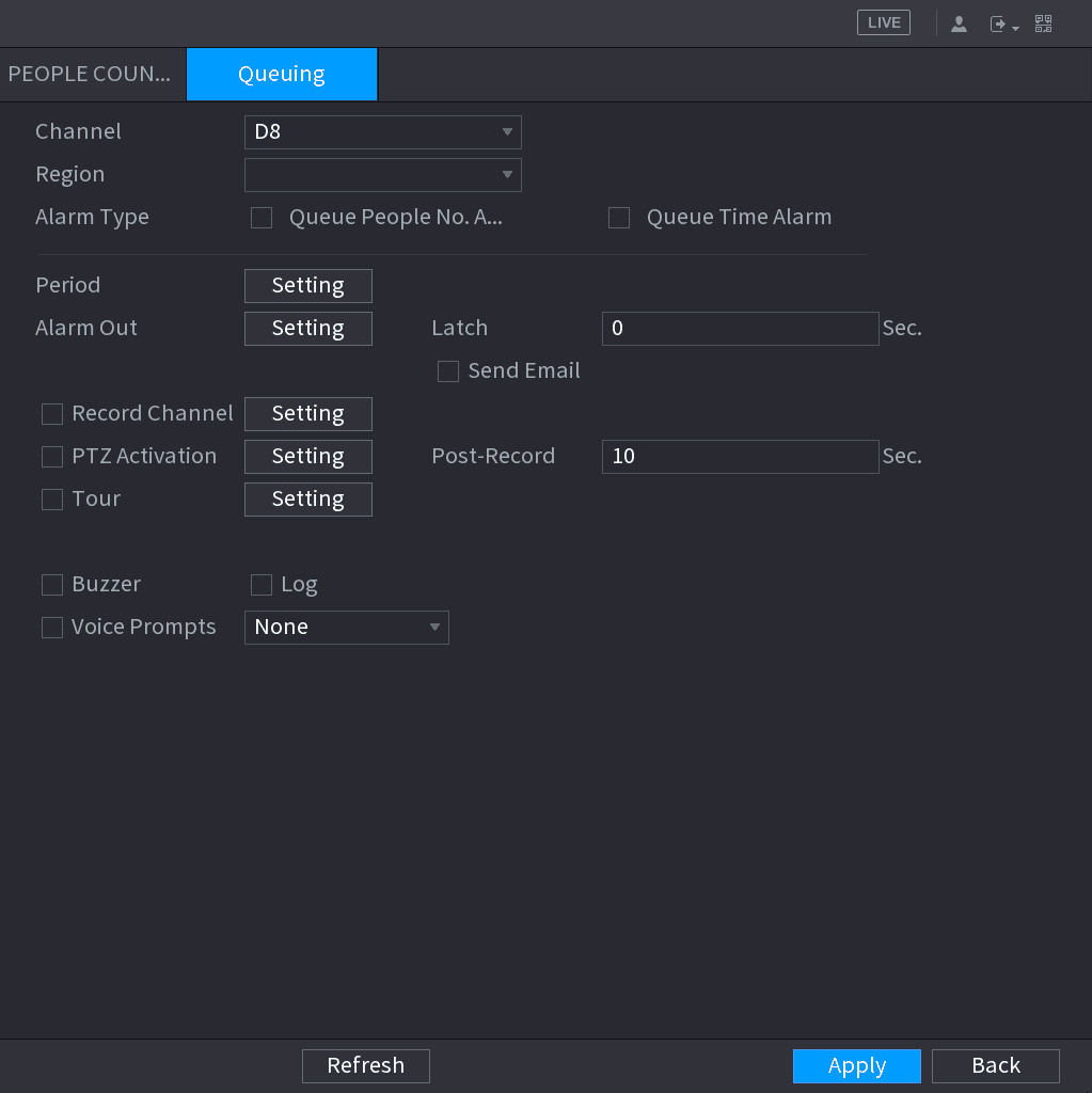
Select Main Menu > AI > PARAMETERS > PEOPLE COUNTING > Queuing. The Queuing interface is displayed. See the figure below.
Configure parameters
Configure parameters. See the table below.
| Parameter | Description |
|---|---|
| Channel | Select a channel from the dropdown list. |
| Region | Set queue detection region. |
| Alarm Type | Select Queue People No. Alarm or Queue Time Alarm. |
| Period | Configure the period and in the set time range, the corresponding configuration item will be linked to start the alarm. |
| Alarm Out | The alarm device (such as lights, sirens, etc.) is connected to the alarm output port. When an alarm occurs, the NVR device transmits the alarm information to the alarm device. |
| Latch | When the alarm ends, the alarm extended for a period of time. The time range is from 0 seconds to 300 seconds. |
| Alarm Upload | Select the check box. When an alarm occurs, the NVR device uploads an alarm signal to the network (including the alarm center). This function is for some series products only. You need to set the alarm center first. For details, see 4.12.9 Alarm Centre. |
| Send Email | Select the check box. When an alarm occurs, the NVR device sends an email to the set mailbox to notify the user. You need to set the email first. For details, see 4.12.6 Email. |
| Record Channel | Select the check box and select the needed recording channel (support multiple choices). When an alarm occurs, the NVR device activates the channel for recording. You need to enable intelligent recording and auto recording first. For details, see 4.1.4.6 Schedule. |
| PTZ Activation | Select the check box and click Setting to select the channel and PTZ action. When an alarm occurs, the NVR device associates the channel to perform the corresponding PTZ action. For example, activate the PTZ in channel one to turn to the preset point X. Tripwire alarm supports to activate PTZ preset point only. You need to set the corresponding PTZ actions first, see 4.4.3 Configuring PTZ Functions. |
| Delay | At the end of the alarm, the recording extends for a period of time. The time range is from 10 seconds to 300 seconds. |
| Tour | Select the check box and select the channel for tour. When an alarm occurs, the local interface of the NVR device displays the selected channel screen. You need to set the time interval and mode for tour first, see 4.16.2 Tour. After the tour is over, the preview interface is restored to the screen split mode before the tour. |
| Log | Select the check box, the NVR device records the alarm information in the log when an alarm occurs. |
| Voice Prompts | Check the box and then select the corresponding audio file from the dropdown list. System plays the audio file when the alarm occurs. Refer to 4.17.1 File Manage to add audio file first. |
| Buzzer | Select the check box to activate the buzzer when an alarm occurs. |
Apply
Click Apply to complete the setup.
Heat map
Heat map technology can monitor the active objects distribution status on the specified zone during a period of time, and use the different colors to display on the heat map.
Open the HEAT MAP interface
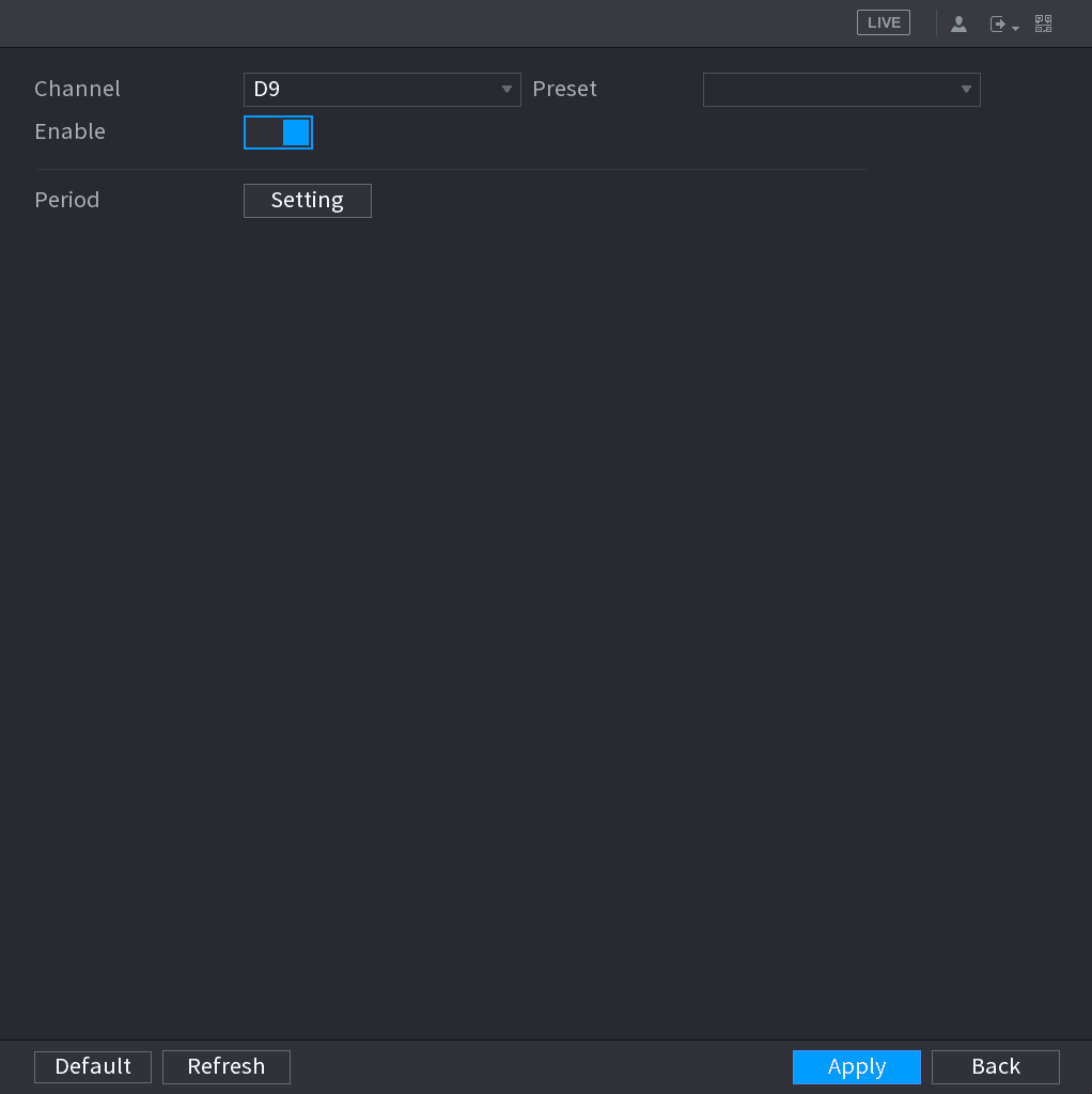
Select Main Menu > AI > PARAMETERS > HEAT MAP. The HEAT MAP interface is displayed. See the figure below.
Select and enable a channel
Select a channel number and then check the box to enable the function.
Open the Setting interface
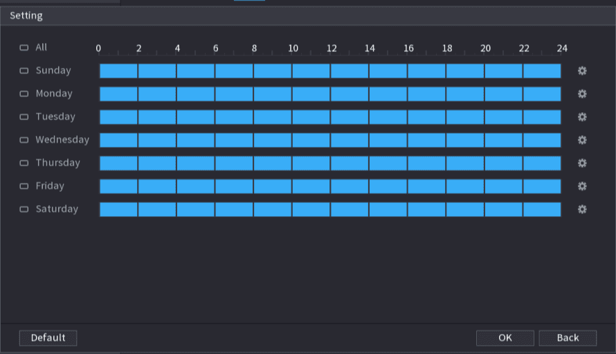
Click Setting button. The Setting interface is displayed. See the figure below.
Set the arm/disarm period
Set arm/disarm period. There are two modes for you to set the period so that the system can detect the specified zone.
⚫ Define the period by drawing.
-
Select the corresponding date and then use mouse to drag the bar to set period.
- Define for the whole week: Click the check box next to All, all the icon switches to the selected state, you can define the period for all the days simultaneously.
- Define for several days of a week: Click the check box before each day one by one, the icon switches to the selected state. You can define the period for the selected days simultaneously.
⚫ Define the period by editing.
- Click the edit icon of the corresponding date, and then set the period on the pop-up interface. Click OK to save. There are six periods for you to set for each day. Under Copy, select All to apply the settings to all the days of a week, or select specific day(s) that you want to apply the settings to.
- Click Apply to save the settings.
Apply
Click Apply button to complete setup.
After set the heat map parameters, go to Main Menu > INFO > EVENT > HEAT MAP to view heat map report. Refer to 4.7.1.8 Heat map for detailed setup information.
ANPR
System uses the video recognition technology to extract the plate number on the surveillance video and then compare it with the specified plate information. System can trigger an alarm once there is a matched result.
You can set different plate recognition rule, alarm linkage actions in different environments (blacklist, whitelist and regular).
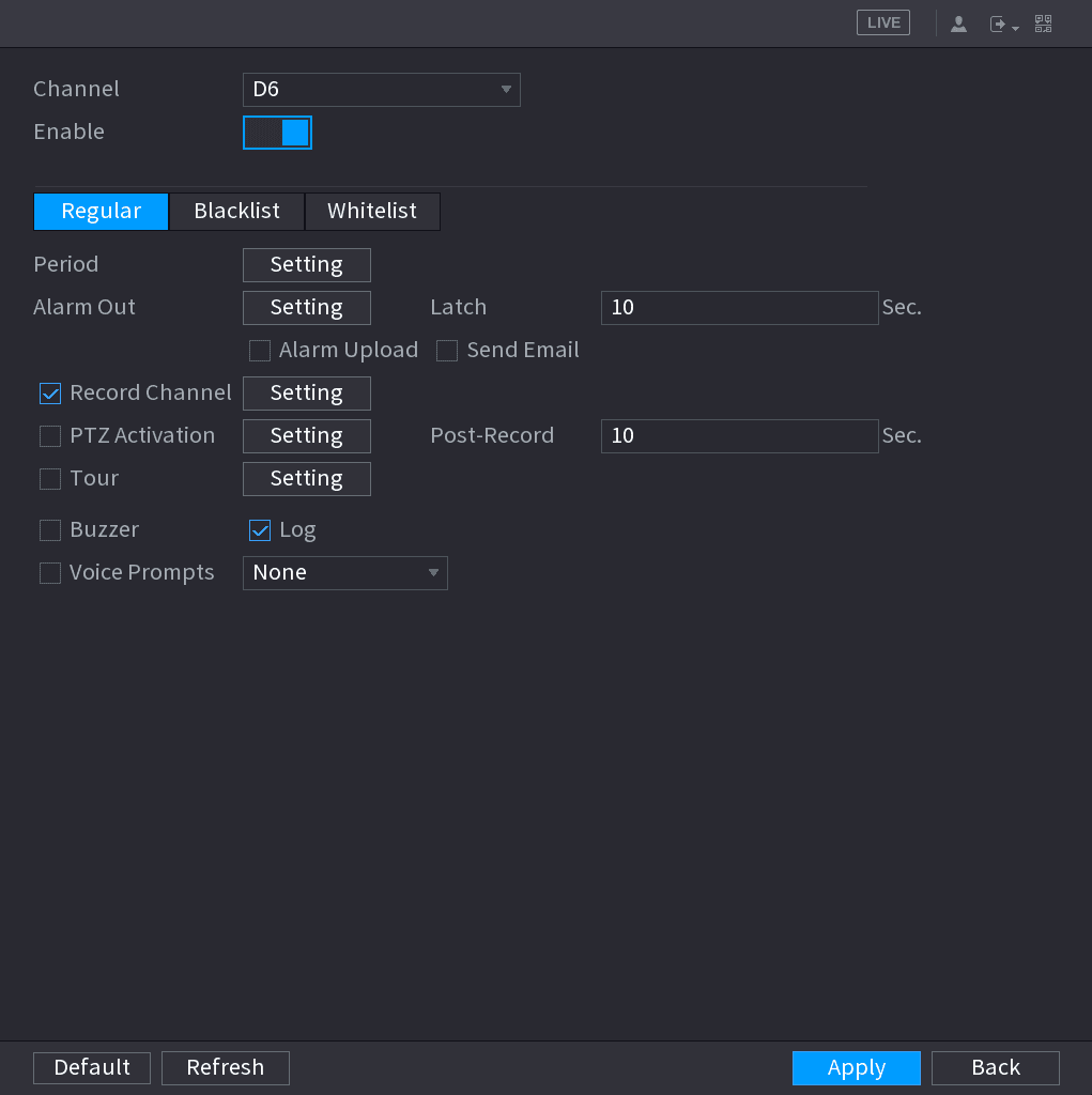
Open the ANPR interface
Select Main Menu > AI > PARAMETERS > ANPR. The ANPR interface is displayed. See the figure below.
Enable ANPR
Select the Enable check box to enable ANPR.
Select a rule tab
Click Regular (default), Blacklist or Whitelist tab to configure it.
Before activate blacklist alarm or whitelist alarm, you need to add the corresponding plate information. Refer to 4.7.3.2 B/W List for detailed information.
- Regular: Device triggers an alarm when it detects any plate number.
- Blacklist: Device triggers an alarm when it detects plate number in the blacklist.
- Whitelist: Device triggers an alarm when it detects plate number in the whitelist.
Set parameters
Set parameters. See the table below.
| Parameter | Description |
|---|---|
| Period | Configure the period and in the set time range, the corresponding configuration item will be linked to start the alarm. |
| Alarm Out | The alarm device (such as lights, sirens, etc.) is connected to the alarm output port. When an alarm occurs, the NVR device transmits the alarm information to the alarm device. |
| Latch | When the alarm ends, the alarm extended for a period of time. The time range is from 0 seconds to 300 seconds. |
| Alarm Upload | Select the check box. When an alarm occurs, the NVR device uploads an alarm signal to the network (including the alarm center). This function is for some series products only. You need to set the alarm center first. For details, see 4.12.9 Alarm Centre. |
| Send Email | Select the check box. When an alarm occurs, the NVR device sends an email to the set mailbox to notify the user. You need to set the email first. For details, see 4.12.6 Email. |
| Record Channel | Select the check box and select the needed recording channel (support multiple choices). When an alarm occurs, the NVR device activates the channel for recording. You need to enable intelligent recording and auto recording first. For details, see 4.1.4.6 Schedule. |
| PTZ Activation | Select the check box and click Setting to select the channel and PTZ action. When an alarm occurs, the NVR device associates the channel to perform the corresponding PTZ action. For example, activate the PTZ in channel one to turn to the preset point X. Tripwire alarm supports to activate PTZ preset point only. You need to set the corresponding PTZ actions first, see 4.4.3 Configuring PTZ Functions. |
| Delay | At the end of the alarm, the recording extends for a period of time. The time range is from 10 seconds to 300 seconds. |
| Tour | Select the check box and select the channel for tour. When an alarm occurs, the local interface of the NVR device displays the selected channel screen. You need to set the time interval and mode for tour first, see 4.16.2 Tour. After the tour is over, the preview interface is restored to the screen split mode before the tour. |
| Log | Select the check box, the NVR device records the alarm information in the log when an alarm occurs. |
| Voice Prompts | Check the box and then select the corresponding audio file from the dropdown list. System plays the audio file when the alarm occurs. Refer to 4.17.1 File Manage to add audio file first. |
| Buzzer | Select the check box to activate the buzzer when an alarm occurs. |
Apply
Click Apply.
AI Search
How to use the Sapphire Series NVR AI Search to find and play back recorded files by face, IVS, human body, vehicle, non-motor vehicle, people counting, and heat map rules.
AI Database
Configure the AI database on the LTS Sapphire Series NVR — create a face library, add face pictures one by one or in batch for face recognition, and manage vehicle plate black/whitelists.