 LTS Connecti abikeskus
Network
Configure the Sapphire Series NVR network settings, including TCP/IP, port, PPPoE, DDNS, UPnP, email, SNMP, multicast, alarm centre, register, P2P, and 802.1X.
You can set NVR network parameters so that the NVR can communicate with devices in the same LAN.
TCP/IP
Select Main Menu > NETWORK > TCP/IP, the TCP/IP interface is displayed. See Figure 4-202.
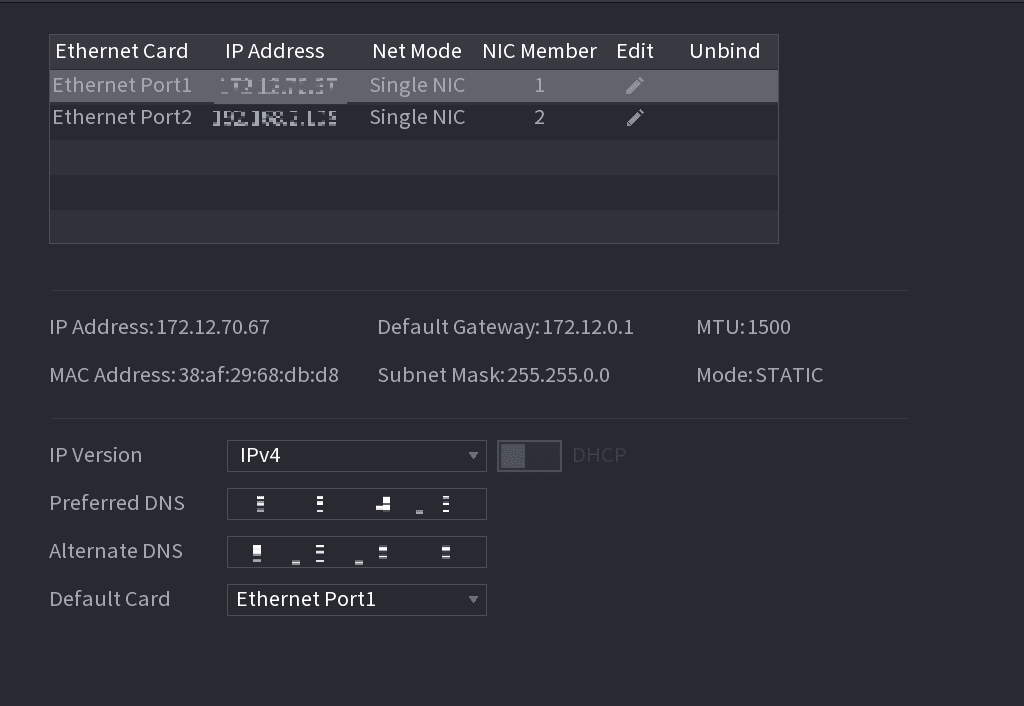
| Parameter | Description |
|---|---|
| Net Mode |
|
| Default Ethernet Port | In the Ethernet Card list, select an Ethernet port as a default port. This setting is available only when the Multi-address is selected in the Net Mode list. |
| IP Version | In the IP Version list, you can select IPv4 or IPv6. Both versions are supported for access. |
| MAC Address | Displays the MAC address of the Device. |
| DHCP | Enable the DHCP function. The IP address, subnet mask and default gateway are not available for configuration once DHCP is enabled.
|
| IP Address | Enter the IP address and configure the corresponding subnet mask and default gateway. |
| Subnet Mask | |
| Default Gateway | IP address and default gateway must be in the same network segment. |
| DNS DHCP | Enable the DHCP function to get the DNS address from router. |
| Preferred DNS | In the Preferred DNS box, enter the IP address of DNS. |
| Alternate DNS | In the Alternate DNS box, enter the IP address of alternate DNS. |
| MTU | In the MTU box, enter a value for network card. The value ranges from 1280 byte through 1500 byte. The default is 1500. The suggested MTU values are as below.
|
| Test | Click Test to test if the entered IP address and gateway are interworking. |
Port
You can configure the maximum connection accessing the Device from Client such as WEB, Platform, and Mobile Phone and configure each port settings.
Open the PORT interface
Select Main Menu > NETWORK > PORT.
The PORT interface is displayed. See Figure 4-203.
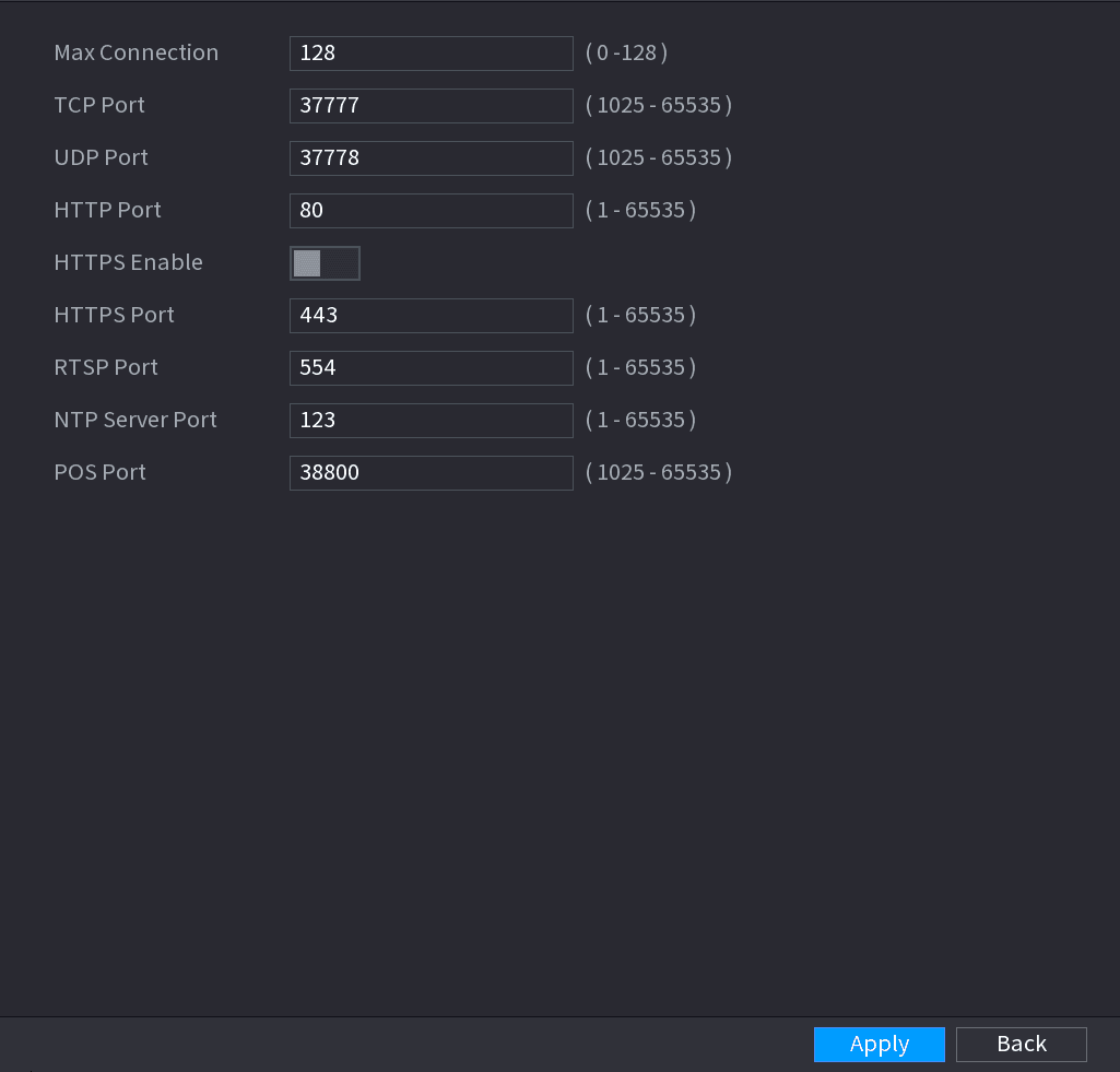
Configure the connection parameters
Configure the settings for the connection parameters. See Table 4-54.
The connection parameters except Max Connection cannot take effects until the Device has been restarted.
| Parameter | Description |
|---|---|
| Max Connection | The allowable maximum clients accessing the Device at the same time, such as WEB, Platform, and Mobile Phone. Select a value between 1 and 128. The default value setting is 128. |
| TCP Port | The default value setting is 37777. You can enter the value according to your actual situation. |
| UDP Port | The default value setting is 37778. You can enter the value according to your actual situation. |
| HTTP Port | The default value setting is 80. You can enter the value according to your actual situation. If you enter other value, for example, 70, and then you should enter 70 after the IP address when logging in the Device by browser. |
| RTSP Port | The default value setting is 554. You can enter the value according to your actual situation. |
| POS Port | Data transmission. The value range is from 1 through 65535. The default value is 38800. |
| HTTPS Enable | Enable HTTPS. |
| HTTPS Port | HTTPS communication port. The default value setting is 443. You can enter the value according to your actual situation. |
Apply the settings
Click Apply to complete the settings.
PPPoE
PPPoE is another way for the Device to access the network. You can establish network connection by configuring PPPoE settings to give the Device a dynamic IP address in the WAN. To use this function, firstly you need to obtain the user name and password from the Internet Service Provider.
Open the PPPoE interface
Select Main Menu > NETWORK > PPPoE.
The PPPoE interface is displayed. See Figure 4-204.
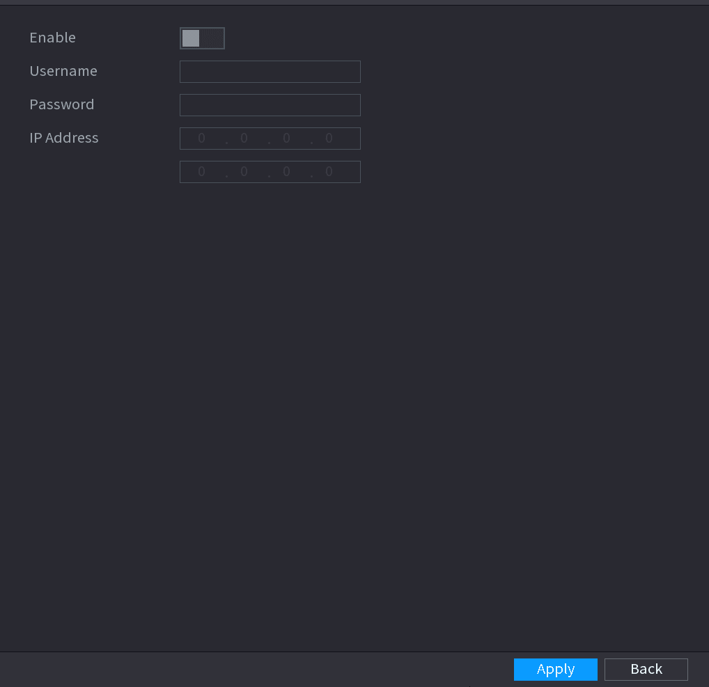
Enable PPPoE
Enable the PPPoE function.
Enter the user name and password
In the User Name box and Password box, enter the user name and password accordingly provided by the Internet Service Provider.
Apply the settings
Click Apply to complete the settings.
The system pops up a message to indicate the successfully saved. The IP address appears on the PPPoE interface. You can use this IP address to access the Device.
When the PPPoE function is enabled, the IP address on the TCP/IP interface cannot be modified.
DDNS
When the IP address of the Device changes frequently, the DDNS function can dynamically refresh the correspondence between the domain on DNS and the IP address, ensuring you access the Device by using the domain.
Preparations
Ensure the Device supports the DDNS Type and log in the website provided by the DDNS service provider to register the information such as domain from PC located in the WAN.
After you have registered and logged in the DDNS website successfully, you can view the information of all the connected devices under this user name.
Configuration Steps
Open the DDNS interface
Select Main Menu > NETWORK > DDNS.
The DDNS interface is displayed. See Figure 4-205.
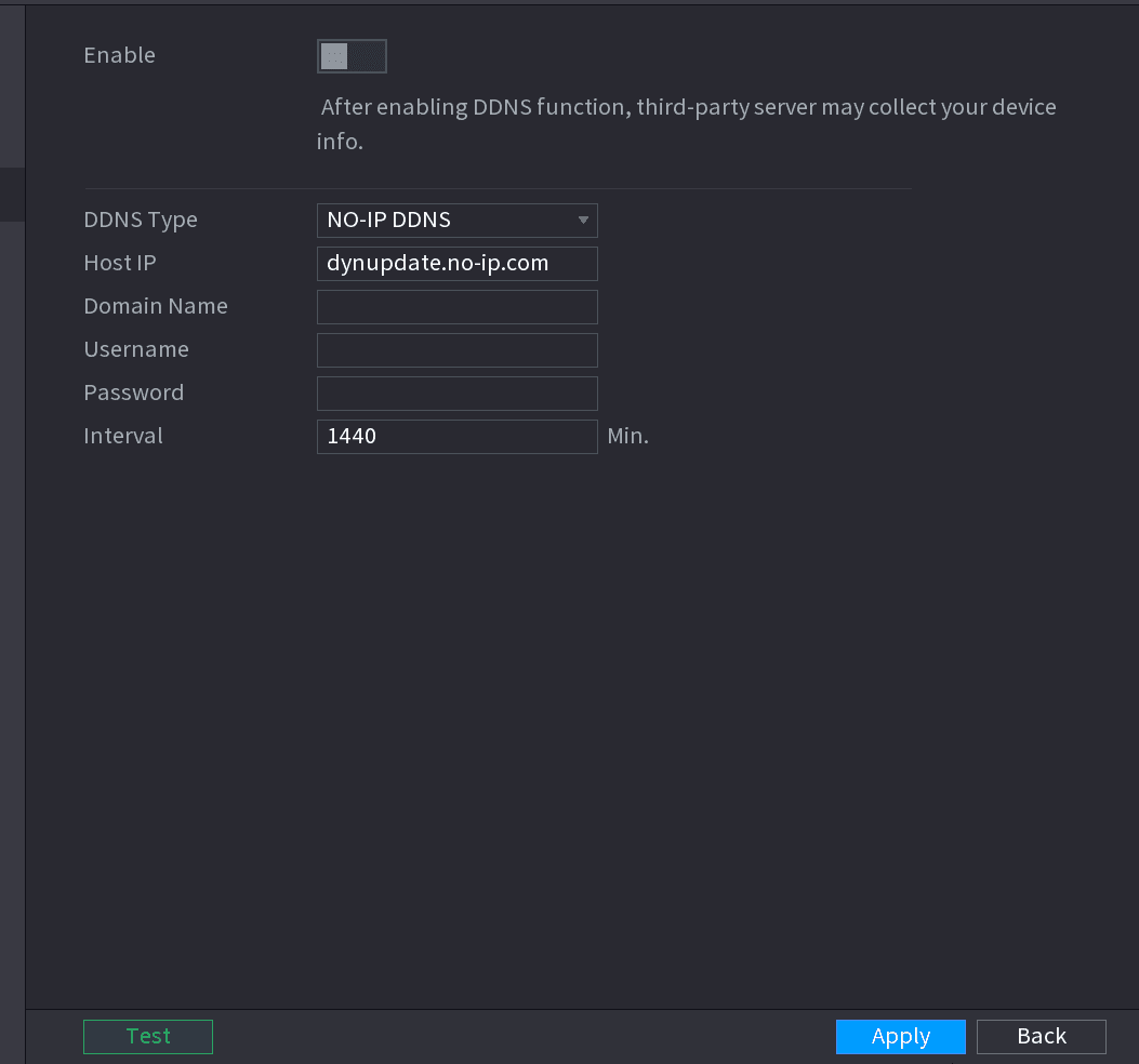
Configure the DDNS parameters
Configure the settings for the DDNS parameters. See Table 4-55.
| Parameter | Description |
|---|---|
| Enable | Enable the DDNS function. After enabling DDNS function, the third-party might collect your Device information. |
| DDNS Type | Type and address of DDNS service provider. |
| Host IP |
|
| Domain Name | The domain name for registering on the website of DDNS service provider. |
| User Name | Enter the user name and password obtained from DDNS service provider. You need to register (including user name and password) on the website of DDNS service provider. |
| Password | |
| Interval | Enter the amount of time that you want to update the DDNS. |
Apply the settings
Click Apply to complete the settings.
Enter the domain name in the browser on your PC, and then press Enter. If the web interface of the Device is displayed, the configuration is successful. If not, the configuration is failed.
UPnP
You can map the relationship between the LAN and the WAN to access the Device on the LAN through the IP address on the WAN.
Preparations
- Login the router to set the WAN port to enable the IP address to connect into the WAN.
- Enable the UPnP function at the router.
- Connect the Device with the LAN port on the router to connect into the LAN.
- Select Main Menu > NETWORK > TCP/IP, configure the IP address into the router IP address range, or enable the DHCP function to obtain an IP address automatically.
Configuration Steps
Open the UPnP interface
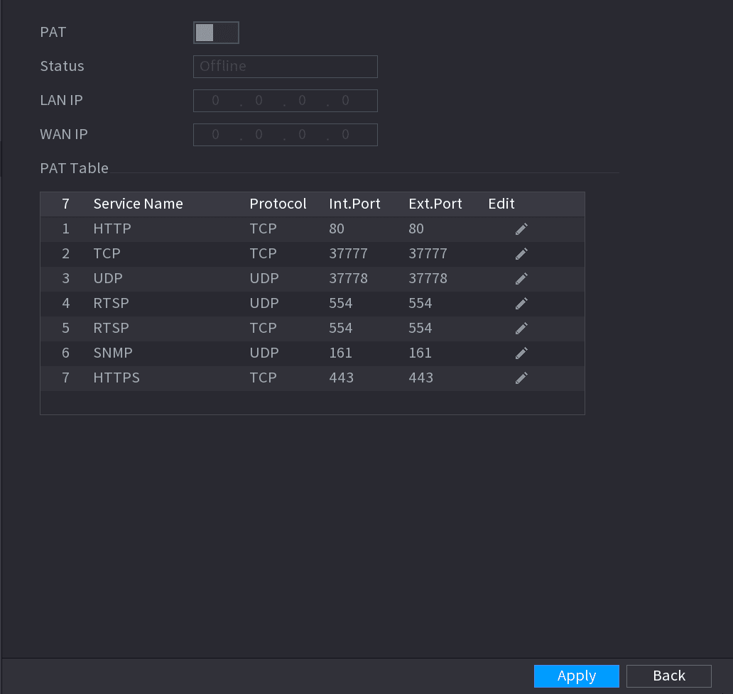
Select Main Menu > NETWORK > UPnP.
The UPnP interface is displayed. See Figure 4-206.
Configure the UPnP parameters
Configure the settings for the UPnP parameters. See Table 4-56.
| Parameter | Description |
|---|---|
| PAT | Enable the UPnP function. |
| Status | Indicates the status of UPnP function.
|
| LAN IP | Enter IP address of router on the LAN. After mapping succeeded, the system obtains IP address automatically without performing any configurations. |
| WAN IP | Enter IP address of router on the WAN. After mapping succeeded, the system obtains IP address automatically without performing any configurations. |
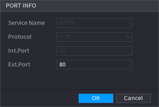
| PAT Table | The settings in PAT table correspond to the UPnP PAT table on the router.
|
Apply the settings
Click Apply to complete the settings.
In the browser, enter http://WAN IP: External IP port. You can visit the LAN Device.
You can configure the email settings to enable the system to send the email as a notification when there is an alarm event occurs.
Open the EMAIL interface
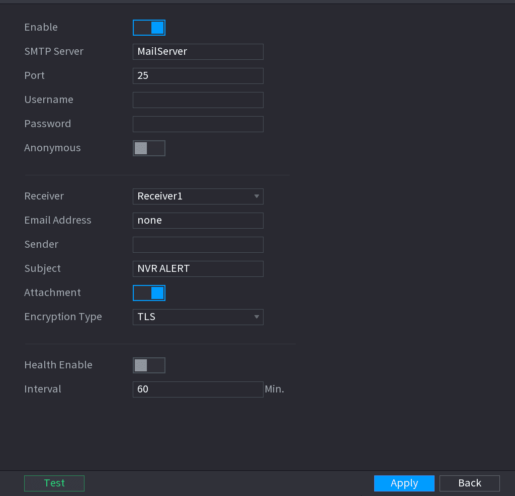
Select Main Menu > NETWORK > EMAIL.
The EMAIL interface is displayed. See Figure 4-208.
Configure the email parameters
Configure the settings for the email parameters. See Table 4-57.
| Parameter | Description |
|---|---|
| Enable | Enable the email function. |
| SMTP Server | Enter the address of SMTP server of sender's email account. |
| Port | Enter the port value of SMTP server. The default value setting is 25. You can enter the value according to your actual situation. |
| User Name | Enter the user name and password of sender's email account. |
| Password | |
| Anonymity | If enable the anonymity function, you can login as anonymity. |
| Mail Receiver | In the Mail Receiver list, select the number of receiver that you want to receive the notification. The Device supports up to three mail receivers. |
| Email Address | Enter the email address of mail receiver(s). |
| Sender | Enter the sender's email address. It supports maximum three senders separated by comma. |
| Title | Enter the email subject. Supports Chinese, English and Arabic numerals. It supports maximum 64 characters. |
| Attachment | Enable the attachment function. When there is an alarm event, the system can attach snapshots as an attachment to the email. |
| Authentication | Select the encryption type: NONE, SSL, or TLS. For SMTP server, the default encryption type is TLS. |
| Interval (Sec.) | This is the interval that the system sends an email for the same type of alarm event, which means, the system does not send an email upon any alarm event. This setting helps to avoid the large amount of emails caused by frequent alarm events. The value ranges from 0 to 3600. 0 means that there is no interval. |
| Health Enable | Enable the health test function. The system can send a test email to check the connection. |
| Interval (Min.) | This is the interval that the system sends a health test email. The value ranges from 30 to 1440. 0 means that there is no interval. |
| Test | Click Test to test the email sending function. If the configuration is correct, the receiver's email account will receive the email. Before testing, click Apply to save the settings. |
Apply the settings
Click Apply to complete the settings.
SNMP
This function is for some series only.
You can connect the Device with some software such as MIB Builder and MG-SOFT MIB Browser to manage and control the Device from the software.
Preparations
- Install the software that can manage and control the SNMP, such as MIB Builder and MG-SOFT MIB Browser
- Obtain the MIB files that correspond to the current version from the technical support.
Configuration Steps
Open the SNMP interface
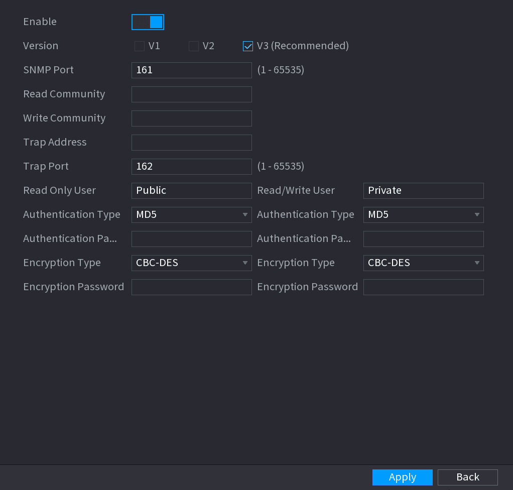
Select Main Menu > NETWORK > SNMP.
The SNMP interface is displayed. See Figure 4-209.
Configure the SNMP parameters
Configure the settings for the SNMP parameters. See Table 4-58.
| Parameter | Description |
|---|---|
| Enable | Enable the SNMP function. |
| Version | Select the check box of SNMP version(s) that you are using. The default version is V3. There is a risk of select V1 or V2. |
| SNMP Port | Indicates the monitoring port on the agent program. |
| Read Community | Indicates the read/write strings supported by the agent program. |
| Write Community | |
| Trap Address | Indicates the destination address for the agent program to send the Trap information. |
| Trap Port | Indicates the destination port for the agent program to send the Trap information. |
| Read Only User | Enter the user name that is allowed to access the Device and has the "Read Only" permission. |
| Read/Write User | Enter the user name that is allowed to access the Device and has the "Read and Write" permission. |
| Authentication Type | Includes MD5 and SHA. The system recognizes automatically. |
| Authentication Password | Enter the password for authentication type and encryption type. The password should be no less than eight characters. |
| Encryption Password | |
| Encryption Type | In the Encryption Type list, select an encryption type. The default setting is CBC-DES. |
Compile the MIB files
Compile the two MIB files by MIB Builder.
Load the module
Run MG-SOFT MIB Browser to load in the module from compilation.
Query the Device
On the MG-SOFT MIB Browser, enter the Device IP that you want to manage, and then select the version number to query.
Obtain the configurations
On the MG-SOFT MIB Browser, unfold the tree-structured directory to obtain the configurations of the Device, such as the channels quantity and software version.
Multicast
When you access the Device from the network to view the video, if the access is exceeded, the video will not display. You can use the multicast function to group the IP to solve the problem.
Open the MULTICAST interface
Select Main Menu > NETWORK > MULTICAST.
The MULTICAST interface is displayed. See Figure 4-210.
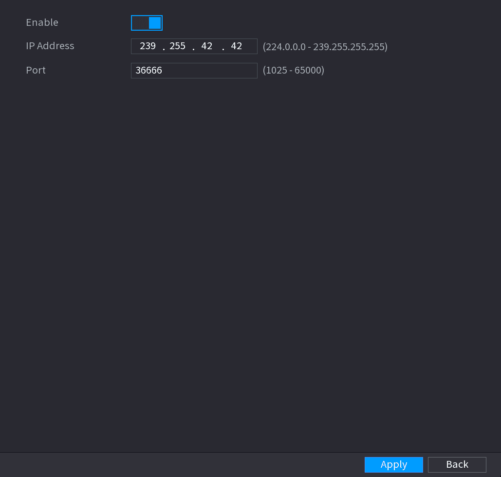
Configure the multicast parameters
Configure the settings for the multicast parameters. See Table 4-59.
| Parameter | Description |
|---|---|
| Enable | Enable the multicast function. |
| IP Address | Enter the IP address that you want to use as the multicast IP. The IP address ranges from 224.0.0.0 through 239.255.255.255. |
| Port | Enter the port for the multicast. The port ranges from 1025 through 65000. |
Apply the settings
Click Apply to complete the settings.
You can use the multicast IP address to login the web. On the web login dialog box, in the Type list, select MULTICAST. The web will automatically obtain the multicast IP address and join. Then you can view the video through multicast function.
Alarm Centre
You can configure the alarm center server to receive the uploaded alarm information. To use this function, the Alarm Upload check box must be selected.
Open the ALARM CENTER interface
Select Main Menu > NETWORK > ALARM CENTER.
The ALARM CENTER interface is displayed. See Figure 4-211.
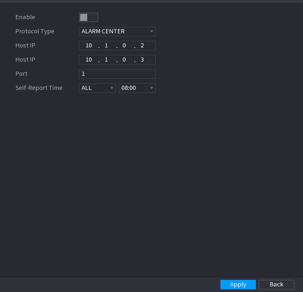
Configure the alarm center parameters
Configure the settings for the alarm center parameters. See Table 4-60.
| Parameter | Description |
|---|---|
| Enable | Enable the alarm center function. |
| Protocol Type | In the Protocol Type list, select protocol type. The default is ALARM CENTER. |
| Host IP | The IP address and communication port of the PC installed with alarm client. |
| Port | |
| Self-Report Time | In the Self-Report Time list, select time cycle and specific time for uploading alarm. |
Apply the settings
Click Apply to complete the settings.
Register
You can register the Device into the specified proxy server which acts as the transit to make it easier for the client software to access the Device.
Open the REGISTER interface
Select Main Menu > NETWORK > REGISTER.
The REGISTER interface is displayed. See Figure 4-212.
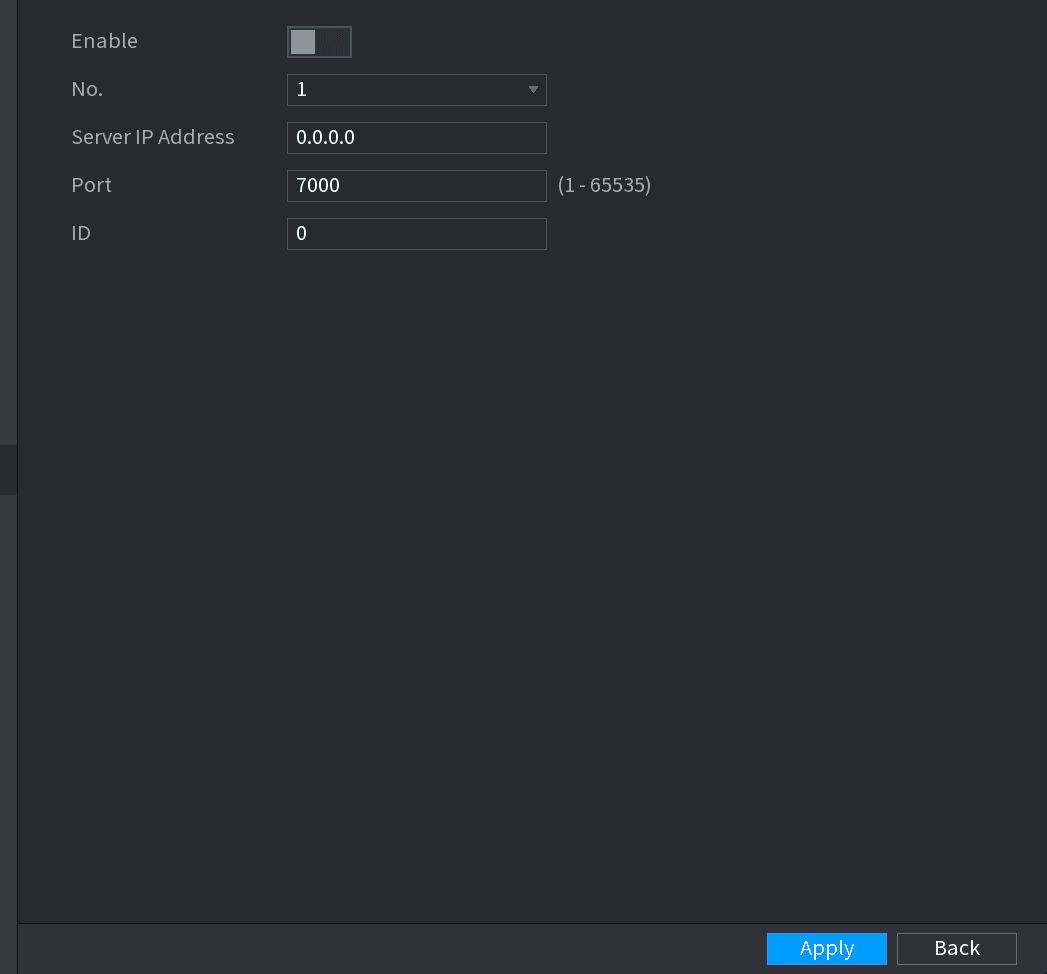
Configure the register parameters
Configure the settings for the register parameters. See Table 4-61.
| Function | Description |
|---|---|
| Enable | Enable the register function. |
| Server IP Address | Enter the server IP address or the server domain that you want to register to. |
| Port | Enter the port of the server. |
| Sub Service ID | This ID is allocated by the server and used for the Device. |
Apply the settings
Click Apply to complete the settings.
P2P
P2P is a kind of convenient private network penetration technology. You do not need to apply for dynamic domain name, doing port mapping or deploying transit server. You can add NVR devices through the below way to achieve the purpose of managing multiple NVR devices at the same time.
- Scan the QR code, download mobile app, and then register an account. For details, see Mobile App Operation.
- Log in www.gotop2p.com, register an account, and then add device via the serial number. For details, see Introduction of P2P Operations.
Connect the NVR device to the Internet, otherwise P2P can not run properly.
Open the P2P interface
Select Main Menu > NETWORK > P2P.
The P2P interface is displayed. See Figure 4-213.
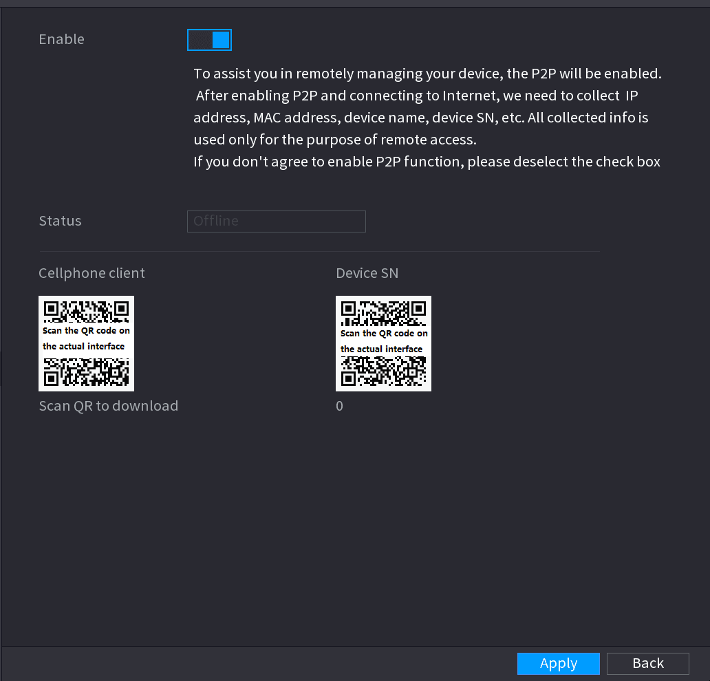
Enable P2P
Enable the P2P function.
After the P2P function is enabled and connected to the Internet, the system will collects your information for remote access, and the information includes but not limited to email address, MAC address, and device serial number.
You can start adding the device.
- Cell Phone Client: Use your mobile phone to scan the QR code to add the device into the Cell Phone Client, and then you can start accessing the Device.
- Platform: Obtain the Device SN by scanning the QR code. Go to the P2P management platform and add the Device SN into the platform. Then you can access and manage the device in the WAN. For details, refer to the P2P operation manual.
You can also enter the QR code of Cell Phone Client and Device SN by clicking on the top right of the interfaces after you have entered the Main Menu.
To use this function, take adding device into Cell Phone Client as an example.
Mobile APP Operation
The following contents are introduced in the example of mobile App.
Download and install the mobile App
Scan the QR code to download and install the mobile App.
Enter the main interface
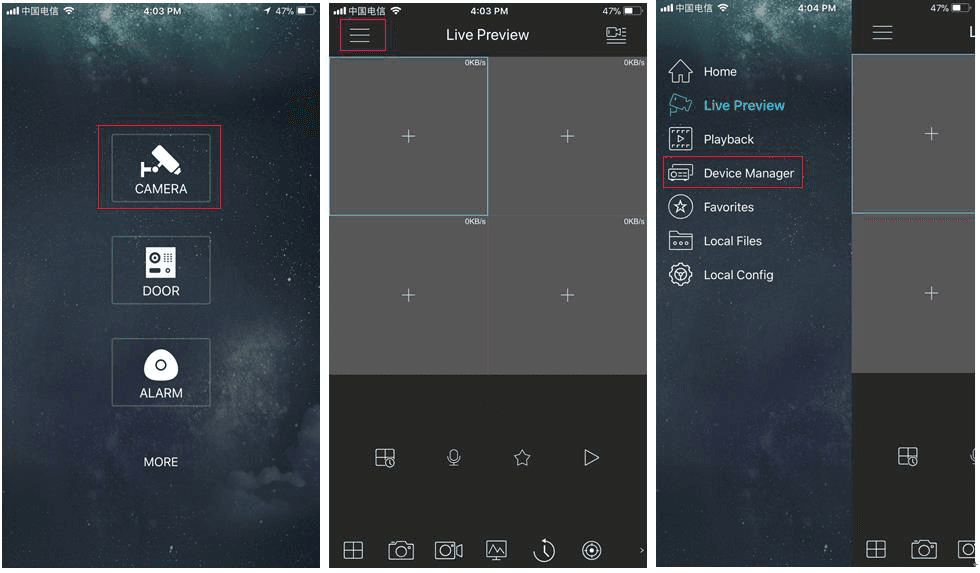
Select Camera and enter the main interface.
Register device in the mobile App
-
Click the menu icon and select Device Manager. See Figure 4-214.
-
Click the add icon and enter the Add Device interface.
Mobile App supports device initialization.
-
Select Wired Device > P2P to enter the P2P interface.
-
Click the QR code icon behind the SN to enter the QR code scan interface.
-
Scan the device label or scan the SN QR code got by selecting Main Menu > Network > P2P. When the scan is successful, the device SN will be displayed in the SN item.
-
Enter name and password.
Start preview
After device registration on mobile App, click Start Preview and you can see the monitor screen.
802.1X
Device needs to pass 802.1x certification to enter the LAN.
Open the 802.1x interface
Select Main Menu > NETWORK > 802.1x.
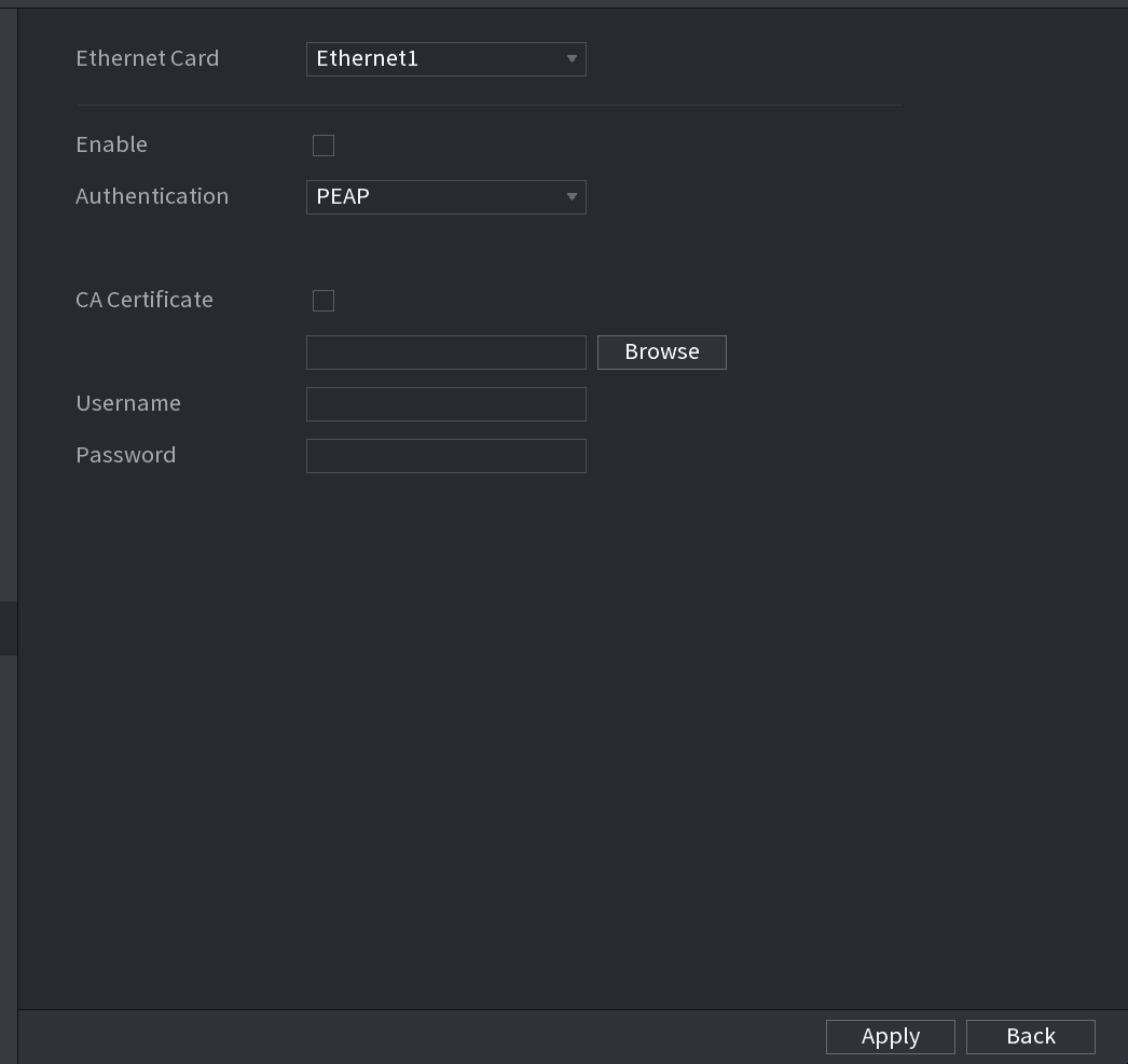
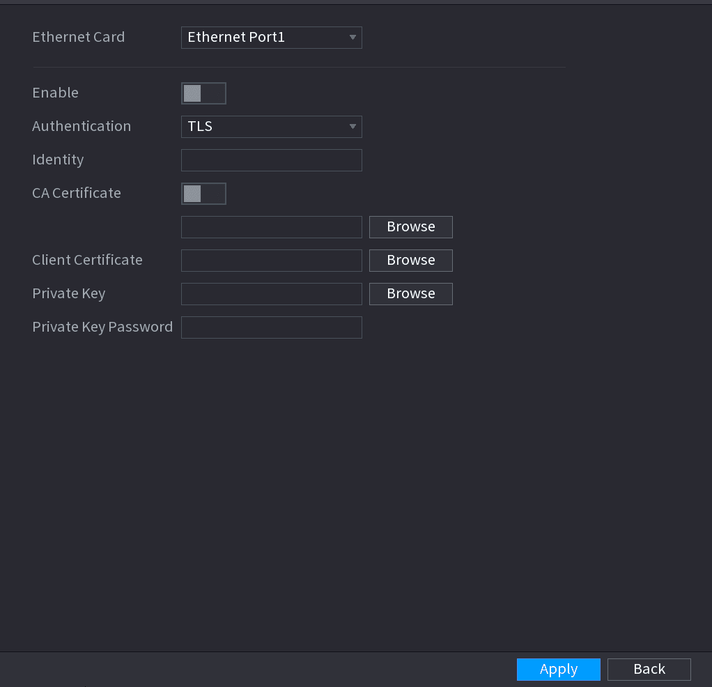
The 802.1x interface is displayed. See Figure 4-215 or Figure 4-216.
Select the Ethernet card
Select the Ethernet card you want to certify.
Enable and configure parameters
Select Enable and configure parameters. See Table 4-62.
| Parameter | Description |
|---|---|
| Authentication |
|
| Identity | It can be configured when Authentication is TLS. |
| CA Certificate | Enable it and click Browse to import CA certificate from flash drive. |
| Username | The username shall be authorized at server. |
| Password | Password of the corresponding username. |
| Client Certificate | When Authentication is TLS, click Browse to import from flash drive. |
| Private Key | |
| Private Key Password | It can be configured when Authentication is TLS. |