 LTS Connect анықтама орталығы
Network Settings
Configure TCP/IP, Guarding Vision, DDNS, PPPoE, NTP, SNMP, Email, and port settings for the Turbo HD DVR GUI 4.0.
Configure TCP/IP Settings
Purpose: TCP/IP settings must be properly configured before operating the device over network.
Go to System > Network > TCP/IP.
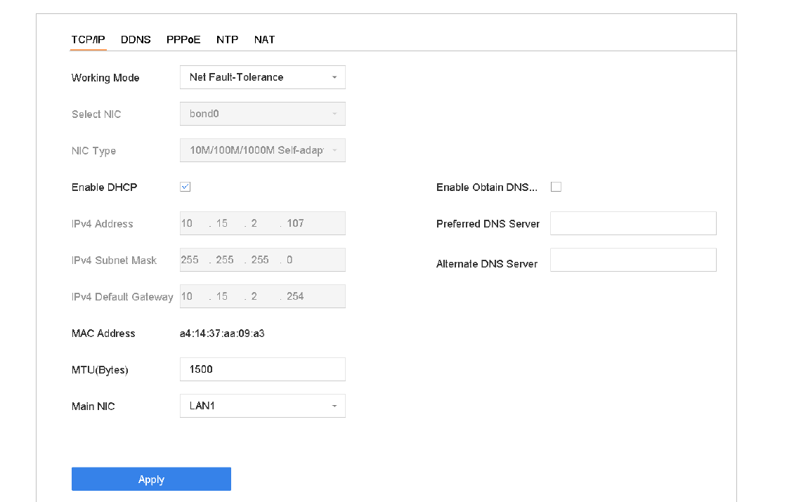
Figure 16-1 TCP/IP Settings
Select Net-Fault Tolerance or Multi-Address Mode under Working Mode.
- Net-Fault Tolerance: The two NIC cards use the same IP address, and you can select the main NIC to LAN1 or LAN2. By this way, in case of one NIC card failure, the device will automatically enable the other standby NIC card so as to ensure the normal running of the whole system.
- Load Balance: By using the same IP address and two NIC cards share the load of the total bandwidth, which enables the system to provide two Gigabit network capacity.
- Multi-address Mode: The parameters of the two NIC cards can be configured independently. You can select LAN1 or LAN2 under Select NIC for parameter settings. You can select one NIC card as default route. And then the system is connecting with the extranet the data will be forwarded through the default route.
Configure other IP settings as needed.
- Check Enable DHCP to obtain IP settings automatically if a DHCP server is available in the network.
- Valid range of MTU value is 500 to 9676.
Click Apply.
Configure Guarding Vision
Purpose: Guarding Vision provides mobile phone application as well as service platform to access and manage your connected devices with remote access to the surveillance system.
Go to Platform Access
Go to System > Network > Advanced > Platform Access.
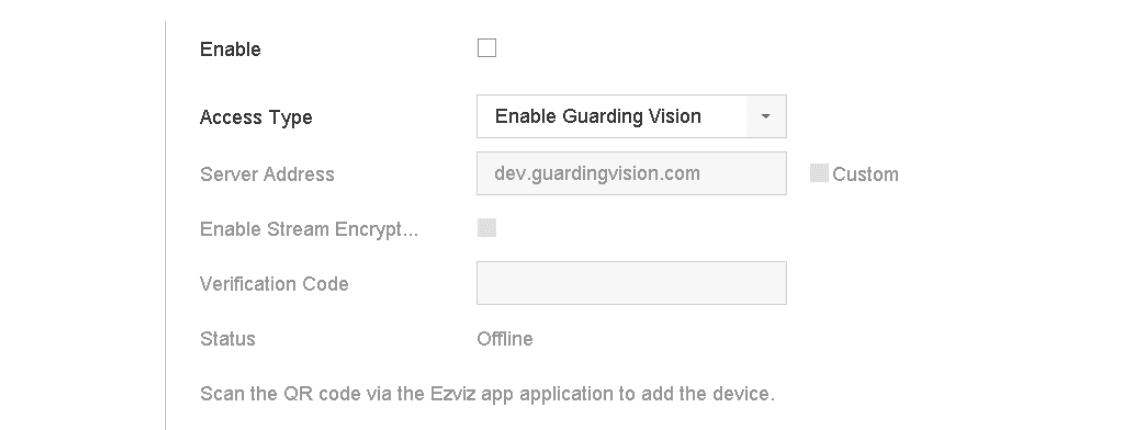
Figure 16-2 Guarding Vision Settings
Enable and create verification code
Check Enable and a Service Terms message box will pop up. Create your verification code, check to agree to the service terms and click OK.
Configure custom server address
(Optional) Check Custom and enter the server address as needed. The default server address is dev.guardingvision.com.
Enable Stream Encryption
(Optional) Check Enable Stream Encryption and verification code will be required for remote access and live view.
Apply
Click Apply.
- After configuration, you can access and manage your devices through Guarding Vision app or dev.guardingvision.com.
- For more detailed instructions of Guarding Vision, please refer to the help on dev.guardingvision.com.
Configure DDNS
Purpose: You can set Dynamic DNS service for network access. Different DDNS modes are available: DynDNS, PeanutHull, and NO-IP.
Before You Start: You must register DynDNS, PeanutHull and NO-IP services with your ISP before configuring DDNS settings.
Go to DDNS settings
Go to System > Network > TCP/IP > DDNS.
Enable DDNS
Check Enable.
Select DDNS type
Select DynDNS under DDNS Type.
PeanutHull and NO-IP are also available under DDNS Type, and required information should be entered accordingly.
Enter server address
Enter Server Address for DynDNS (i.e. members.dyndns.org).
Enter device domain name
Under Device Domain Name, enter the domain name obtained from the DynDNS website.
Enter credentials
Enter the User Name and Password registered in the DynDNS website.
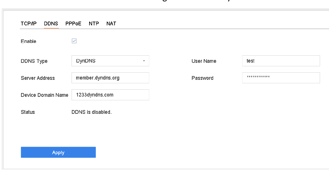
Figure 16-3 DDNS Settings
Apply
Click Apply.
Configure PPPoE
If the device is connected to Internet through PPPoE, you need to configure user name and password accordingly under System > Network > TCP/IP > PPPoE.
Contact your Internet service provider for details about PPPoE service.
Configure NTP
Purpose: Connection to a network time protocol (NTP) server can be configured on your device to ensure the accuracy of system date and time.
Go to NTP settings
Go to System > Network > TCP/IP > NTP.
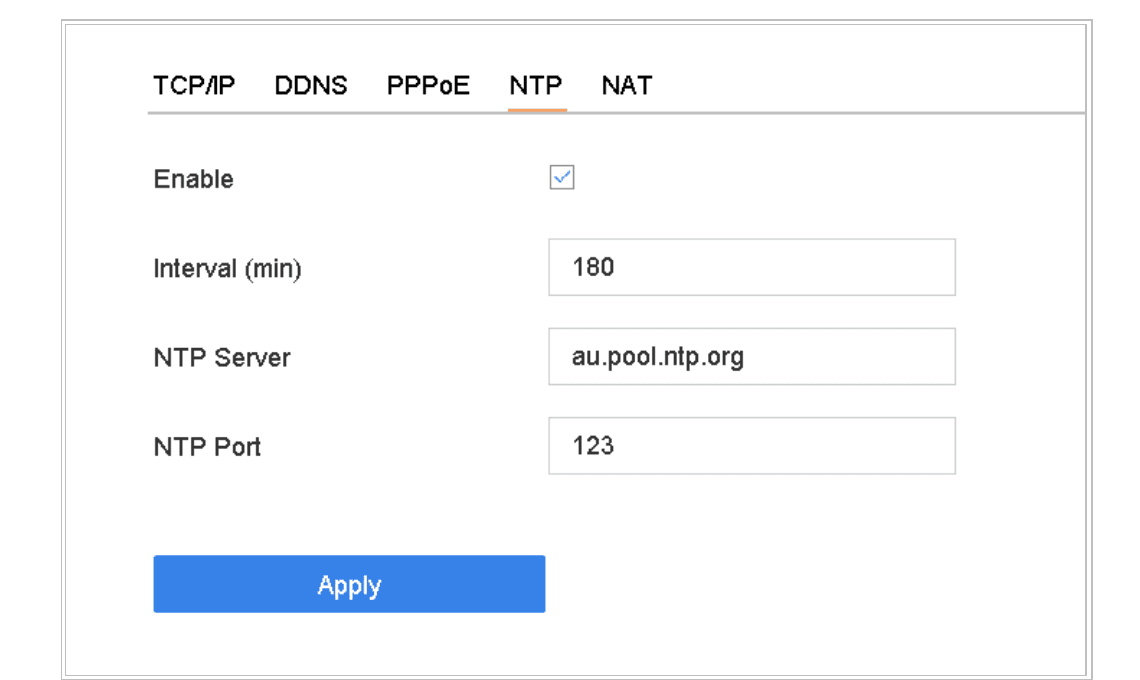
Figure 16-4 NTP Settings
Enable NTP
Check Enable.
Configure NTP parameters
Configure NTP settings as needed.
- Interval (min): Time interval between two time synchronizations with NTP server.
- NTP Server: IP address of the NTP server.
- NTP Port: Port of the NTP server.
Apply
Click Apply.
Configure SNMP
Purpose: You can configure SNMP settings to get device status and parameter information.
Before You Start: Download the SNMP software to receive device information via SNMP port. By setting the trap address and port, the device is allowed to send alarm event and exception message to the surveillance center.
Go to SNMP settings
Go to System > Network > Advanced > SNMP.
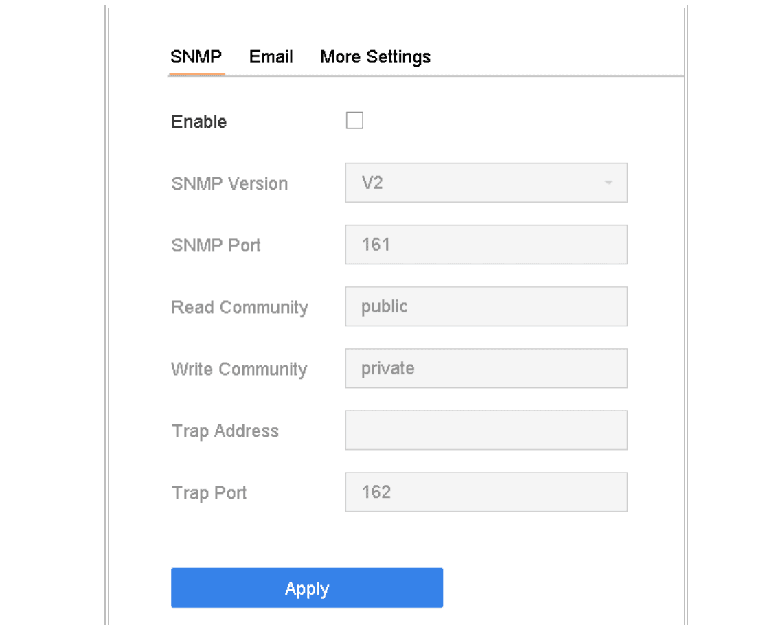
Figure 16-5 SNMP Settings
Enable SNMP
Check Enable. A message box will pop up to prompt possible security risk and click Yes to continue.
Configure SNMP settings
Configure the SNMP settings as needed.
- Trap Address: IP address of the SNMP host.
- Trap Port: Port of the SNMP host.
Apply
Click Apply.
Configure Email
Purpose: The system can send an Email to designated users when a specified event occurs, such as an alarm or motion event is detected, or the administrator password is changed, etc.
Before You Start: The device must be connected to a local area network (LAN) that contains an SMTP mail server. The network must be connected to either an intranet or the Internet depending on the location of the e-mail accounts to send notification.
Go to Email settings
Go to System > Network > Advanced > Email.
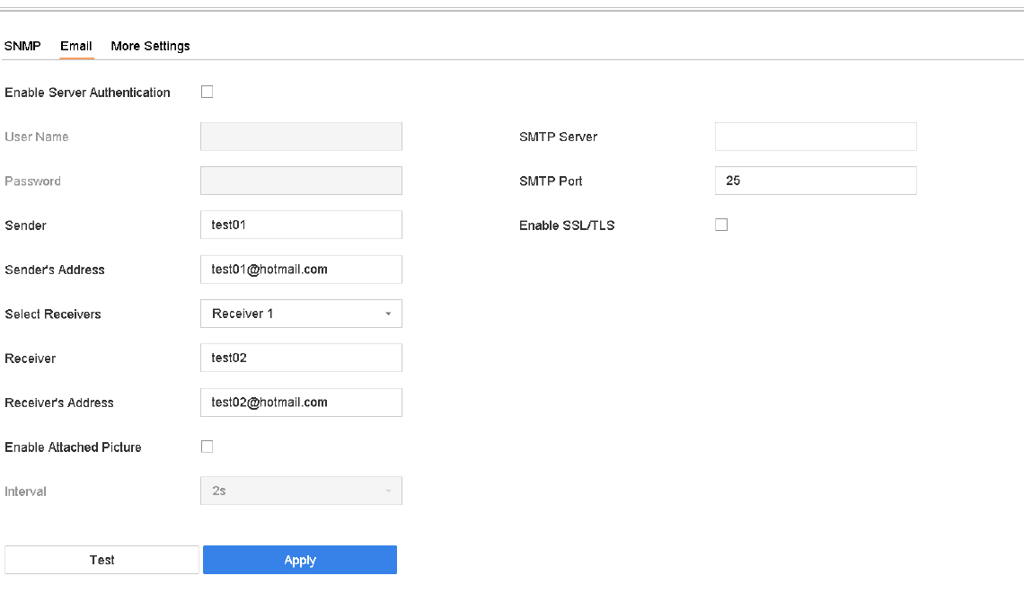
Figure 16-6 Email Settings
Configure Email parameters
Configure the following Email settings.
- Enable Server Authentication: Check to enable the function if the SMTP server requires user authentication and enter user name and password accordingly.
- SMTP Server: The IP address of SMTP Server or host name (e.g., smtp.263xmail.com).
- SMTP Port: The SMTP port. The default TCP/IP port used for SMTP is 25.
- Enable SSL/TLS: Check to enable SSL/TLS if required by the SMTP server.
- Sender: The name of the sender.
- Sender's Address: Sender's Address.
- Select Receivers: Select the receiver. Up to 3 receivers can be configured.
- Receiver: The name of the receiver.
- Receiver's Address: The Email address of user to be notified.
- Enable Attached Picture: Check to enable the function if you want to send email with attached alarm images. The interval is the time between two adjacent alarm images.
Apply
Click Apply.
Test email
(Optional) Click Test to send a test email.
Configure Ports
You can configure different types of ports to enable relevant functions.
Go to System > Network > Advanced > More Settings and configure port settings as needed.
- Alarm Host IP/Port: With a remote alarm host configured, the device will send the alarm event or exception message to the host when an alarm is triggered. The remote alarm host must have the client management system (CMS) software installed. The Alarm Host IP refers to the IP address of the remote PC on which the CMS software (e.g., iVMS-4200) is installed, and the Alarm Host Port (7200 by default) must be the same as the alarm monitoring port configured in the software.
- Server Port: Server port (8000 by default) should be configured for remote client software access and its valid range is 2000 to 65535.
- HTTP Port: HTTP port (80 by default) should be configured for remote web browser access.
- Multicast IP: Multicast can be configured to enable live view for cameras that exceed the maximum number allowed through network. A multicast IP address covers Class-D IP ranging from 224.0.0.0 to 239.255.255.255 and it is recommended to use the IP address ranging from 239.252.0.0 to 239.255.255.255. When adding a device to the CMS software, the multicast address must be the same as that of the device.
- RTSP Port: RTSP (Real Time Streaming Protocol) is a network control protocol designed for use in entertainment and communications systems to control streaming media servers. The port is 554 by default.
- Output Bandwidth Limit: You can check the checkbox to enable output bandwidth limit.
- Output Bandwidth: After enable the output bandwidth limit, input the output bandwidth.
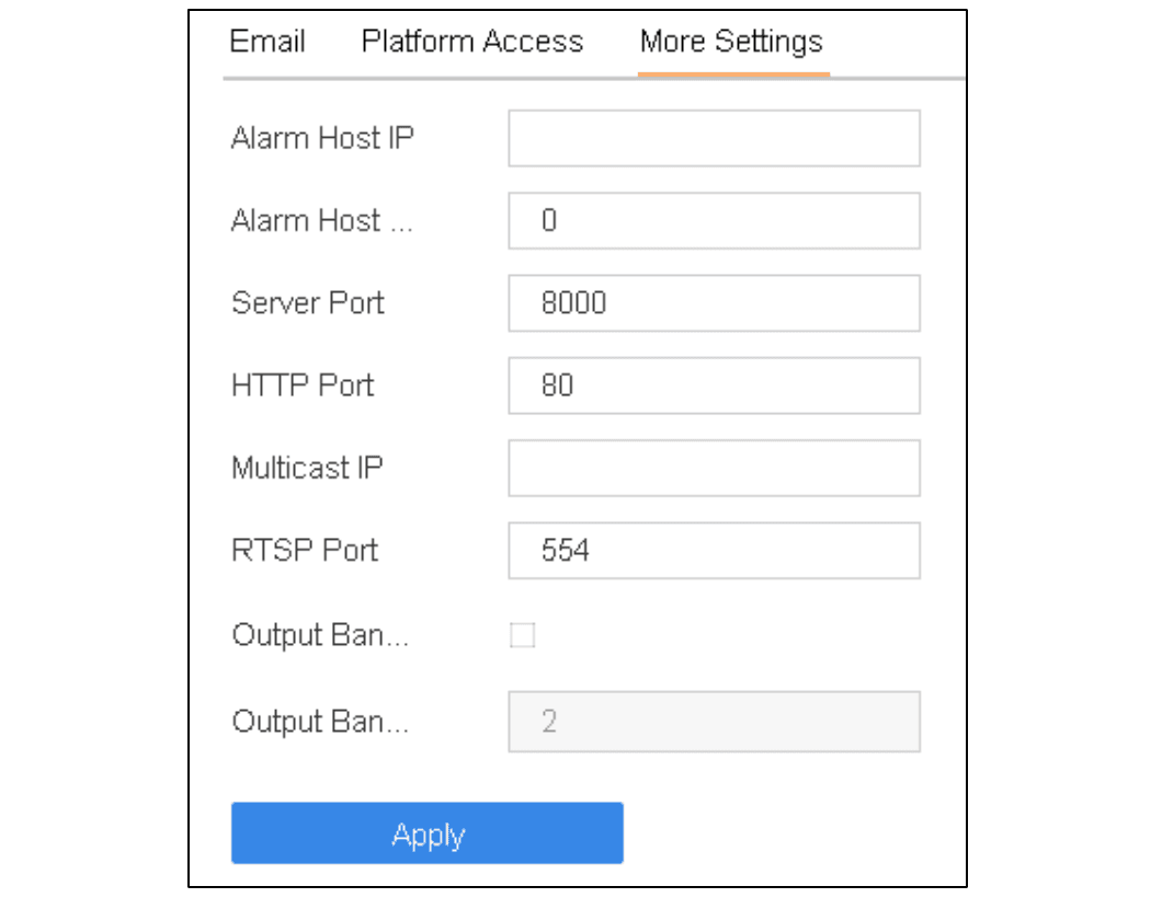
Figure 16-7 Port Settings
- The output bandwidth limit is used for the remote live view and playback.
- The default output bandwidth is the maximum limit.
Human Body Detection
Configure and use smart analysis and human body search features, including enabling smart analysis tasks, searching by appearance or picture, and managing sample pictures on the Turbo HD DVR GUI 4.0.
System Maintenance
Procedures for storage device maintenance, log search and export, configuration import/export, firmware upgrade, restoring defaults, and system service settings on the Turbo HD DVR GUI 4.0.