 LTS Connect анықтама орталығы
Device Installation
How to unpack, inspect, and install the NVR hardware, including HDD installation for each chassis series, CD-ROM installation, and rear-panel connection samples.
All the installation and operations here should conform to your local electric safety rules.
Device Installation Diagrams
Please refer to the following diagrams to install the NVR.
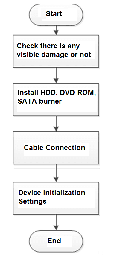
Check Unpacked NVR
When you receive the NVR from the forwarding agent, please check whether there is any visible damage. The protective materials used for the package of the NVR can protect most accidental clashes during transportation. Then you can open the box to check the accessories.
Please check the items in accordance with the list. Finally you can remove the protective film of the NVR.
About Front Panel and Rear Panel
The model number in the stick on the bottom of NVR is very important; please check according to your purchase order.
The label in the rear panel is very important too. Usually we need you to represent the serial number when we provide the service after sales.
HDD Installation
For the first time installation, make sure whether the HDD has been installed or not. We recommend to use HDD of enterprise level or surveillance level. It is not recommended to use PC HDD.

- Shut off the power before you replace the HDD.
- Use the dedicated SATA HDD for monitoring recommended by the HDD manufacturer.
- You can refer to the Appendix for HDD space information and recommended HDD brand.
Smart 1U Series
Connect cable and then secure the HDD on the NVR if it is not convenient to connect the HDD data cable and power cable at first.
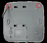
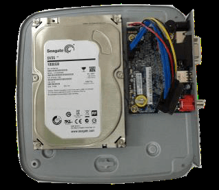
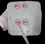
Connect the cables
Connect the HDD cable and power cable to the HDD and the mainboard respectively.
Replace the cover
Put the cover back and then fix the screws of the rear panel. The installation is complete.
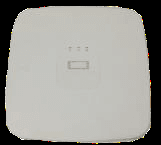
Mini 1U/Cooper 1U/Compact 1U Series
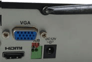
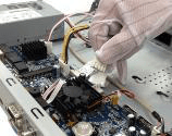
Connect the cable to the mainboard
Connect the one end of the HDD data cable and the power cable to the mainboard.
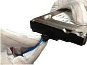
Connect the cable to the HDD
Connect the other end of the HDD data cable and the power cable to the HDD.
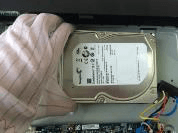
Secure the HDD
Turn the device upside down; fix the screws to secure the HDD on the bottom of the chassis.
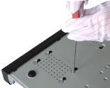
Replace the cover
Put the cover in accordance with the clip and then fix the screws on the rear panel and side panel.
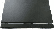
1U Series
The following figures are based on the professional 1U with 8 PoE ports series.
Connect cable and then secure the HDD on the NVR if it is not convenient to connect the HDD data cable and power cable at first.
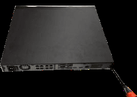
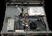
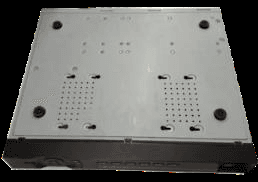
Secure the HDD
Turn the device upside down and then secure the screws firmly. It is to fix the HDD on the chassis.
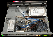
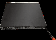
Replace the cover
Put the cover in accordance with the clip and then fix the screws on the rear panel and side panel.
1.5U Series
Remove the front cover
Use the screwdriver to loose the screws of the rear panel and then remove the front cover.
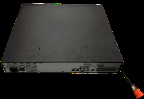
Secure the HDD to the bracket
Put the HDD to the HDD bracket in the chassis and then line up the four screws to the four holes in the HDD. Use the screwdriver to fix the screws firmly to secure HDD on the HDD bracket.
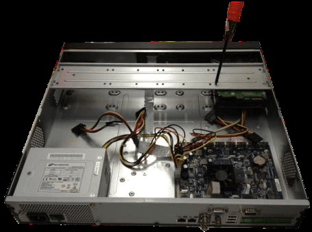
Connect the cables
Connect to the HDD data cable to the main board and the HDD port respectively. Loosen the power cable of the chassis and connect another end of the power cable to the HDD port.
Replace the front cover
After connect the cable, put the front cover back to the device and then fix screws of the rear panel.
General 2U Series
Remove the front cover
Use the screwdriver to loose the screws of the rear panel and then remove the front cover.
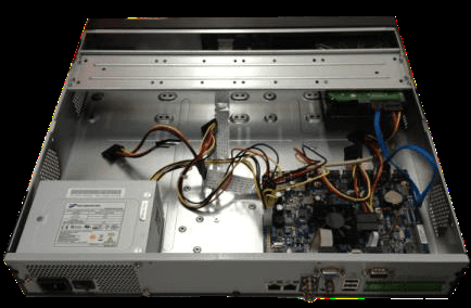
Secure the HDD to the bracket
Put the HDD to the HDD bracket in the chassis and then line up the four screws to the four holes in the HDD. Use the screwdriver to fix the screws firmly to secure HDD on the HDD bracket.
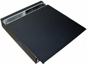
Connect the cables
Connect to the HDD data cable to the main board and the HDD port respectively. Loosen the power cable of the chassis and connect another end of the power cable to the HDD port.
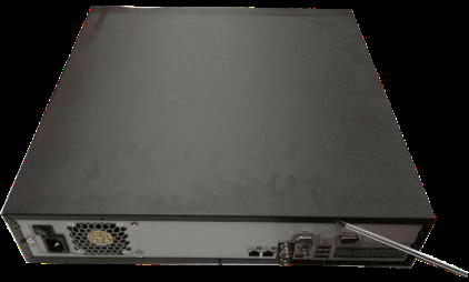
Replace the front cover
After connect the cable, put the front cover back to the device and then fix screws of the rear panel.
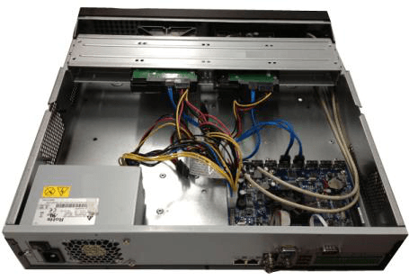
Beneficio Vertical 1U Series
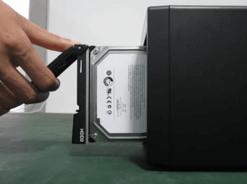
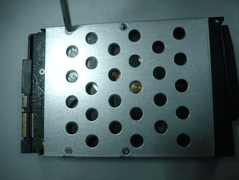
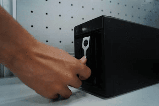
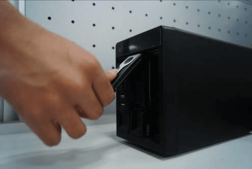
Pull the HDD knob up
Pull the HDD knob up when you put the HDD into the box in case the knob buckle may strike the front panel.
CD-ROM Installation
Please follow the steps listed below.
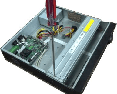
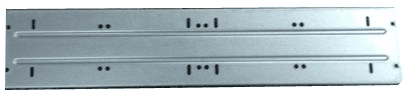
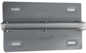
Install a pair of CD-ROM brackets
Install a pair of the CD-ROM bracket. Please make sure the reverse side is secure too.
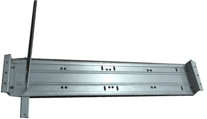
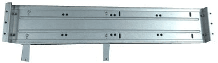
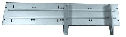
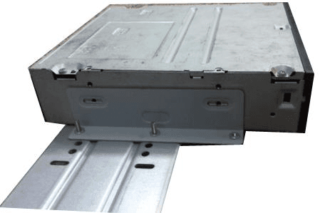
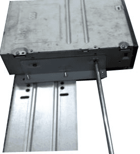
Put the bracket back
Put the bracket back. Please adjust the CD-ROM to the proper position so that the button of the front panel is directly facing the pop-up button of the CD-ROM.
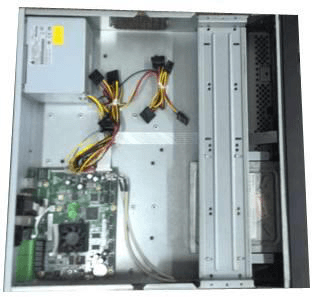
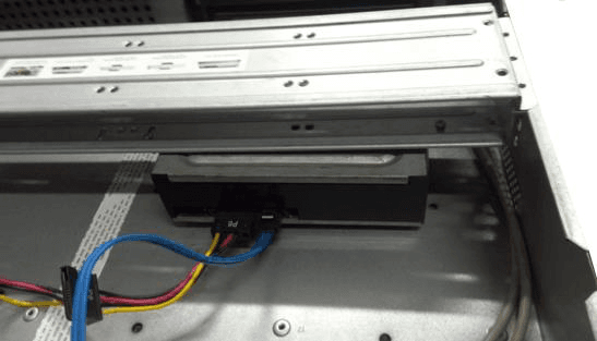
Secure and close
Secure the HDD bracket and put the top cover back.
Connection Sample
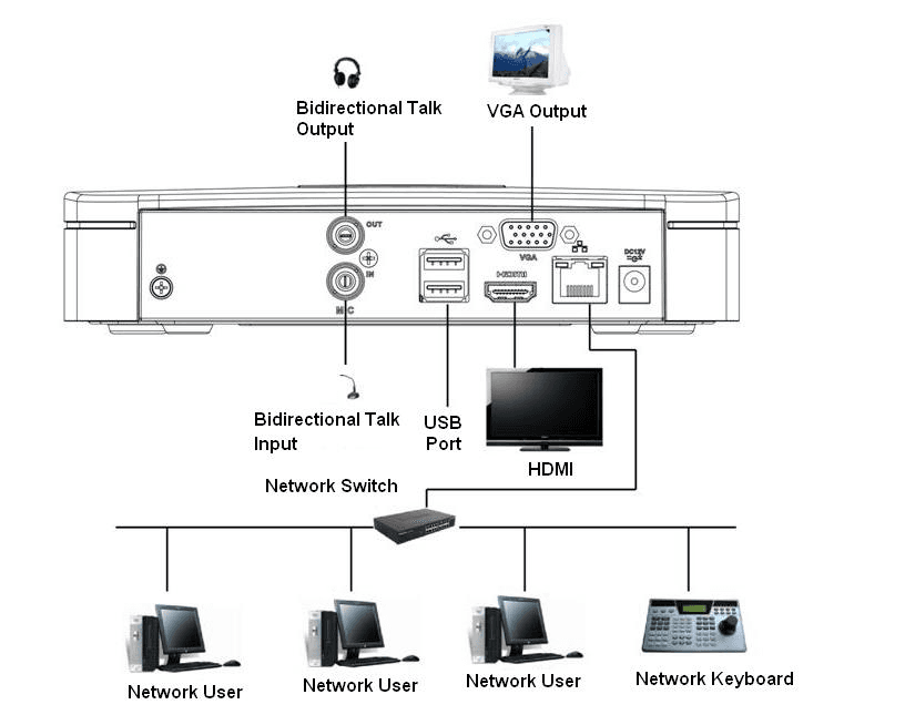
Beneficio Smart 1U/Beneficio Smart 1U(S2)/ 4K Smart 1U (S2) Series
Please refer to Figure 3-1 for connection sample.
The following figure for reference only.
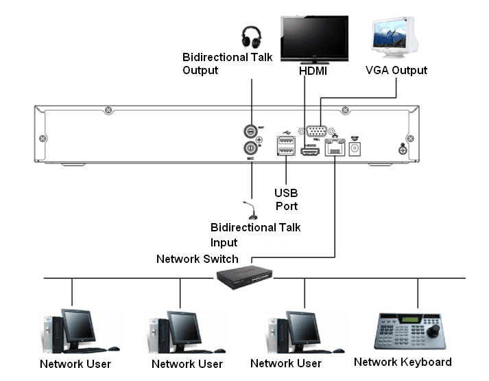
Beneficio Mini 1U / Beneficio Mini 1U with 4 PoE Ports / Beneficio mini 1U with 8 PoE Ports Series
Please refer to Figure 3-2 for connection sample.
The following figure for reference only.
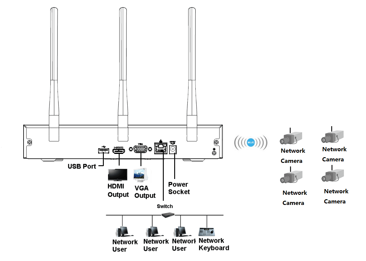
Smart 1U / Compact 1U Wireless Series
Please refer to Figure 3-3 for connection sample.
The following figure for reference only.
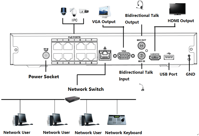
Compact 1U(S2)/4K Compact 1U (S2) / Cooper 1U (S3) / Cooper 1U (S3) with 4 PoE Ports / Compact 1U (S3) with 8 PoE Ports Series
Please refer to Figure 3-4 for connection sample.
The following figure for reference only.
Beneficio 1U (S2) Series
Please refer to Figure 3-5 for connection sample.
The following figure for reference only.
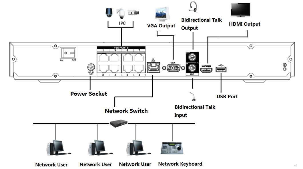
Beneficio Entry-level 1U Series
Please refer to Figure 3-6 for connection sample.
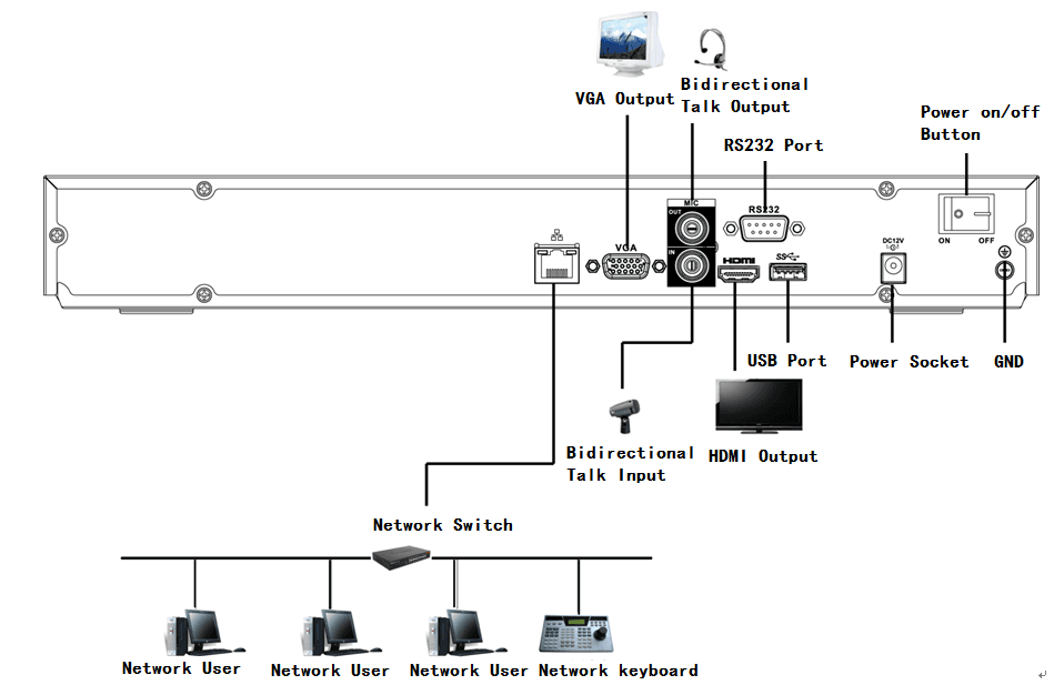
Beneficio 1U/Professional 4K 1U/ Professional 4K 1U with 8 PoE ports/ Professional 4K 1U with 16 PoE ports/4K 1U (S2) with 24 PoE Ports/4K 1U (S2E) with 8 PoE Ports/4K 1U (S2E) with 16 PoE Ports Series
Please refer to Figure 3-7 for connection sample.
The following figure for reference only.
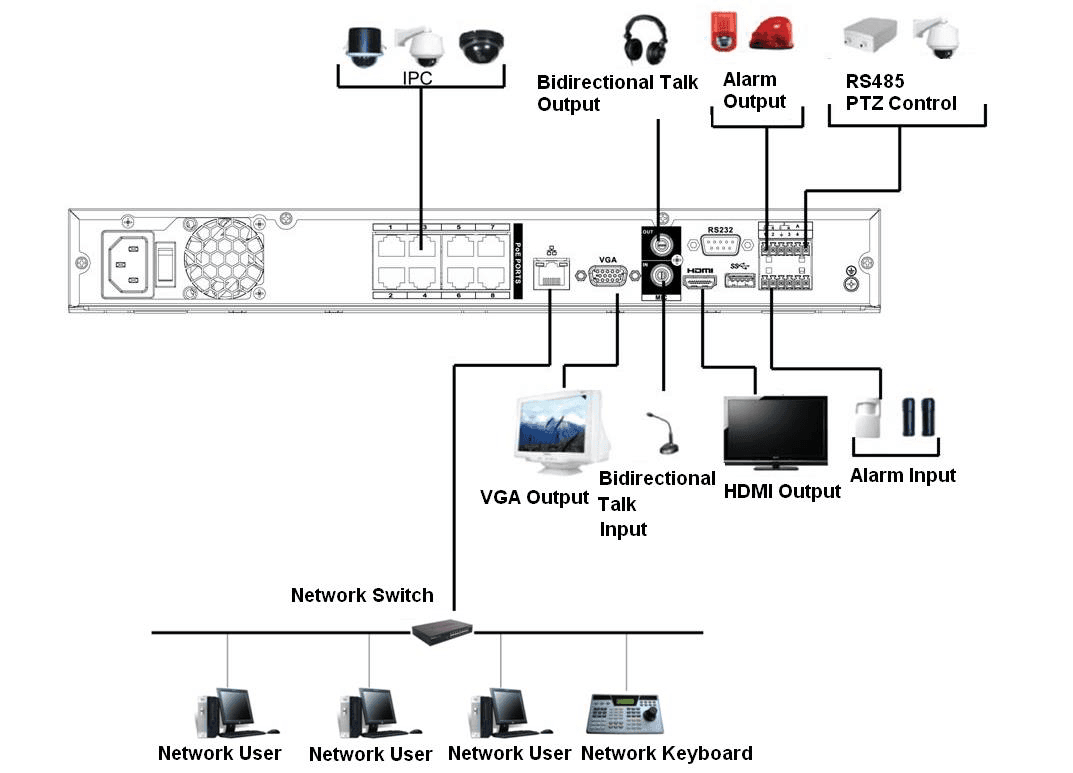
General 4K 1U (S2)/Beneficio 4K 1U with 8 PoE ports/4K 1U (S2) with 4 PoE ports/4K 1U (S2) with 8 PoE ports/4K 1U (S2) with 16 PoE ports Series
Please refer to Figure 3-8 for connection sample.
The following figure for reference only.
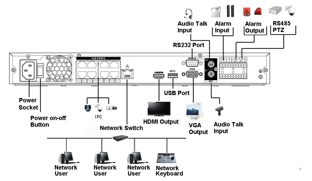
Professional 4K 1.5U/ Professional 4K 1.5U with 16 PoE ports/ Professional 4K 2U / Professional 4K 2U with 16 PoE ports/4K 1.5U (S2E) with 16 PoE ports/4K 2U (S2E) with 16 PoE Ports Series
Please refer to Figure 3-8 for connection sample.
The following figure for reference only.
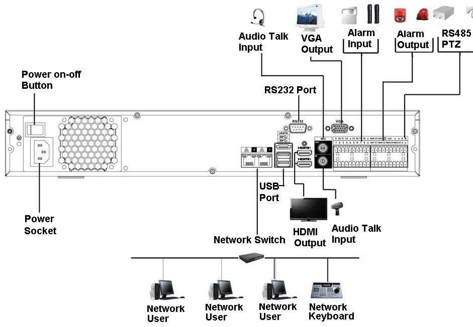
Beneficio 1.5U / Beneficio 1.5U with 8 PoE ports / Beneficio 1.5U with 16 PoE ports/4K 1.5U (S2) Series
Please refer to Figure 3-10 for connection sample.
The following figure for reference only.
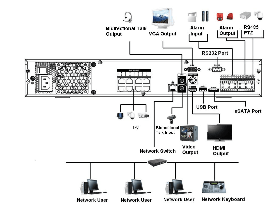
4K 2U (S2) Series
Please refer to Figure 3-11 for connection sample.
The following figure for reference only.
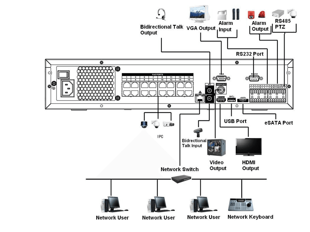
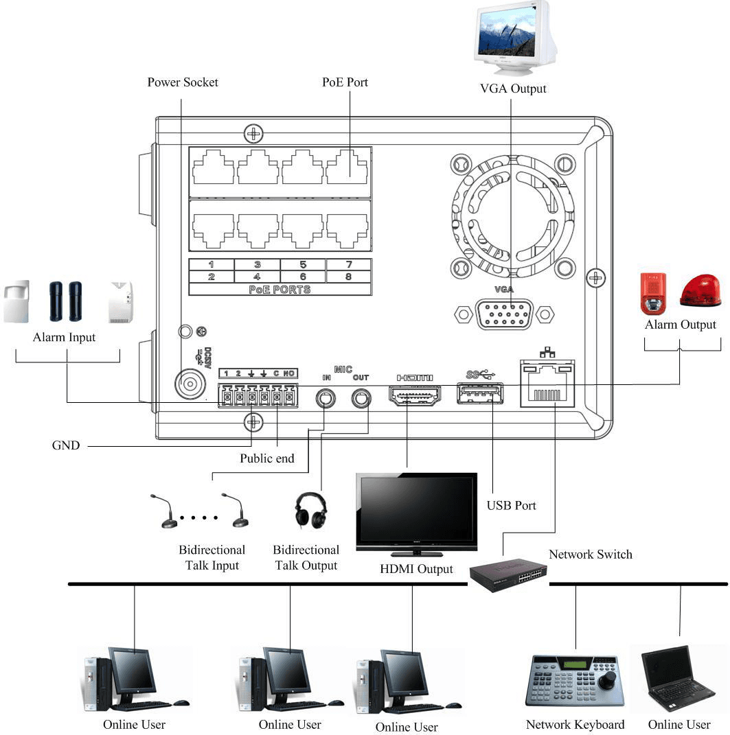
Beneficio Vertical 1U Series
Please refer to Figure 3-12 for connection sample.
Front Panel and Rear Panel
Front panel indicators, buttons, and rear panel ports for every Sapphire Series NVR model, including indicator light tables and port connection tables for each chassis and PoE variant.
Getting Started
Boot up the LTS Sapphire NVR and complete device initialization — set the time zone, create the admin password, configure the unlock pattern, and set up password protection.