 LTS Connect 도움말 센터
Smart Detection
Configure SMD, human face detection, and IVS smart detection on the CVI DVR to detect persons, vehicles, faces, and behaviors and trigger alarms.
Smart detection includes SMD, human face and IVS.
The system processes and analyzes video images, abstracts key information from the video, and activates alarms when it detects that person, vehicle, face or behavior matches the detection rule.
- Not all models support this function.
- Only the analog channel 1 supports this function. The IP channel does not support this function.
- SMD, face detection function, and IVS function cannot be enabled at the same time.
SMD
The system processes and analyzes video images, effectively detects persons and vehicles in the video, and activates alarms. Meanwhile, the system carries out structured storage of the detection result, to search it quickly in the future.
Configuring SMD Settings
Set SMD parameters. When the Device detects information, the system activates alarms.
Open the SMD interface
Select Main Menu > SMART DETECTION > PARAMETERS > SMD.
The SMD interface is displayed.
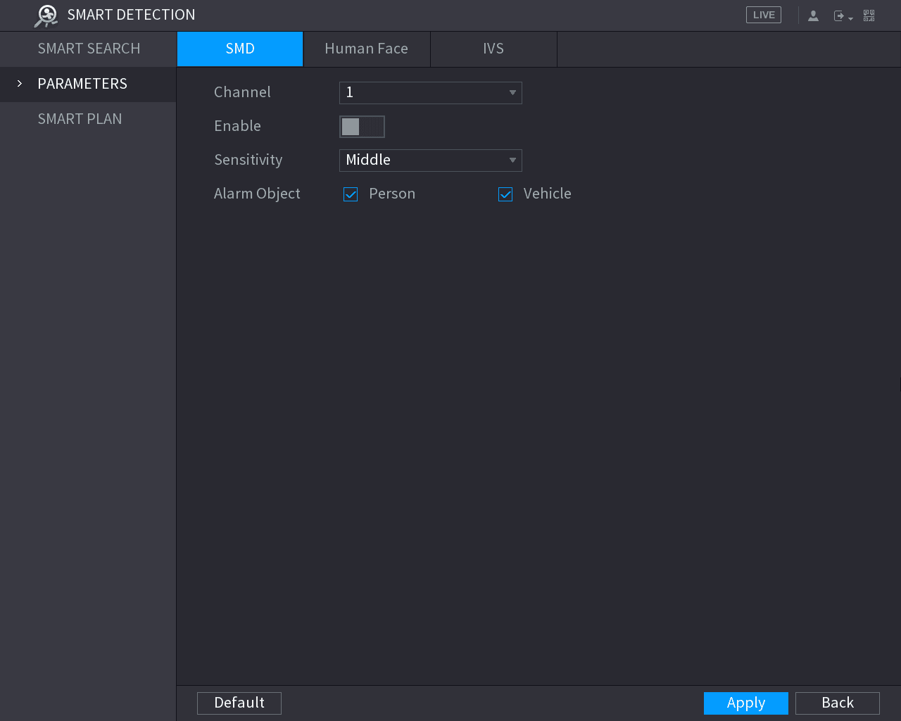
Select the channel and enable
Select the channel and enable.
Set parameters
Set parameters.
| Parameter | Description |
|---|---|
| Sensitivity | Set sensitivity, including high, middle, and low. The higher the sensitivity is, the bigger alarm probability will be, the bigger false alarm rate will be. The system selects middle by default. |
| Alarm object | Select alarm object, including person and vehicle. |
Save the configuration
Click Apply to save configuration.
Smart Search
Filter SMD videos that meet criteria and play back the videos.
Open the SMD search interface
Select Main Menu > SMART DETECTION > SMART SEARCH > SMD.
The SMD interface is displayed.
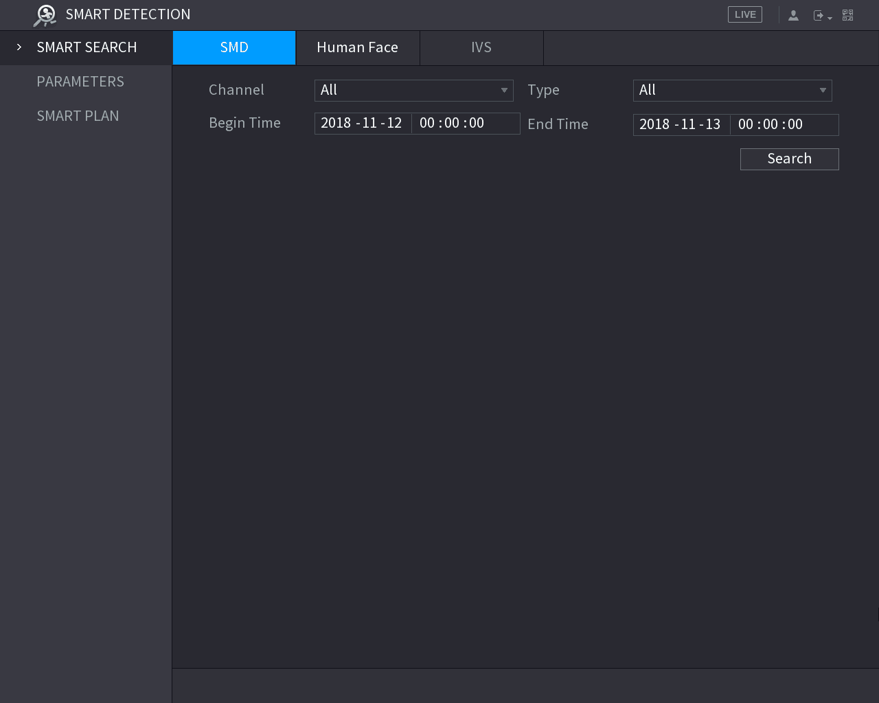
Search
Select channel, type, begin time and end time, and then click Search.
The search result is displayed.
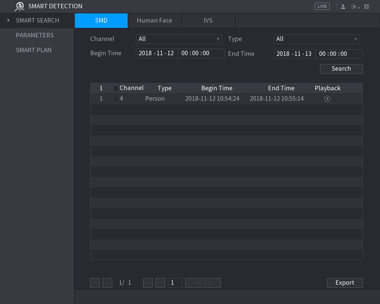
- Click the play icon to play back the video.
- Tick the check box before the video, and then click Export to export the video to external USB.
Configuring Face Detection
You can configure the face detection settings and search the detected faces in the defined time period.
- Not all models support this function.
- Only the analog channel 1 supports this function. The IP channel does not support this function.
- SMD, face detection function, and IVS function cannot be enabled at the same time.
Configuring Face Detection Settings
When the Device detects the human faces, the system activates alarms.
Open the Human Face interface
Select Main Menu > SMART DETECTION > PARAMETERS > Human Face.
The Human Face interface is displayed.
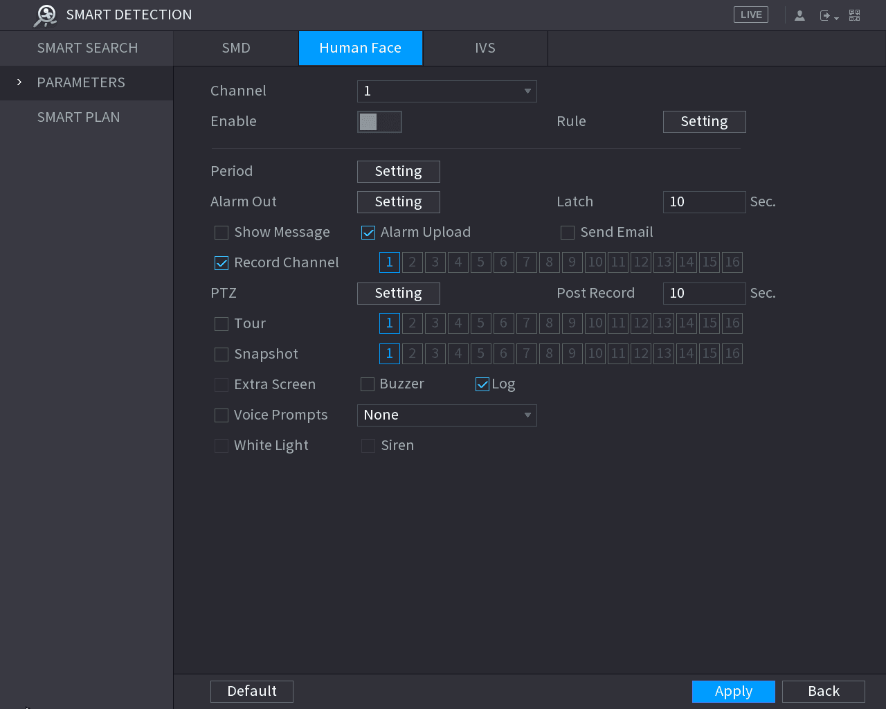
Configure the face detection parameters
Configure the settings for the face detection parameters.
| Parameter | Description |
|---|---|
| Channel | In the Channel list, select the channel that you want to configure the face detection settings. Only the analog channel 1 supports this function. |
| Enable | Enable or disable the face detection function. |
| Rule | Click Setting to draw areas to filter the target. You can configure two filtering targets (maximum size and minimum size). When the target is smaller than the minimum size or larger than the maximum size, no alarms will be activated. The maximum size should be larger than the minimum size. |
| Period | Define a period during which the detection is active. For details, see "Setting Motion Detection Period" section in "5.10.4.1 Configuring Motion Detect Settings." |
| Alarm Out | Click Setting to display setting interface. Enable alarm activation function. Select the alarm output port(s) to which the peripheral alarm devices are connected. When an alarm event occurs, the system links the peripheral alarm devices connected to the selected output port. |
| Latch | Set a length of time for the Device to delay turning off alarm after the external alarm is cancelled. The value ranges from 0 seconds to 300 seconds. If you enter 0, there will be no delay. |
| Show Message | Select the Show Message check box to enable a pop-up message in your local host PC. |
| Alarm Upload | Select the Alarm Upload check box to enable the system to upload the alarm signal to the network (including alarm center) when an alarm event occurs. |
| Send Email | Select the Send Email check box to enable the system to send an email notification when an alarm event occurs. To use this function, make sure the email function is enabled in Main Menu > NETWORK > EMAIL. |
| Record Channel | Select the channel(s) that you want to record. The selected channel(s) starts recording after an alarm event occurs. The recording for intelligence event and auto recording function must be enabled. For details, see "5.1.4.9 Configuring Recorded Video Storage Schedule" and "5.9.1 Enabling Record Control." |
| PTZ | Click Setting to display the PTZ interface. Enable PTZ linkage actions, such as selecting the preset that you want to be called when an alarm event occurs. Face Detect can only link PTZ preset. |
| Post Record | Set a length of time for the Device to delay turning off recording after the alarm is cancelled. The value ranges from 10 seconds to 300 seconds. |
| Tour | Select the Tour check box to enable a tour of the selected channels. |
| Snapshot | Select the Snapshot check box to take a snapshot of the selected channel. To use this function, make sure the following settings are configured: - The snapshot function is enabled for motion detect alarms in Main Menu > STORAGE > SCHEDULE > Snapshot. - Select Main Menu > CAMERA > ENCODE > Snapshot, in the Mode list, select Human Face. |
| Extra Screen | Select the check box to enable the function. When an alarm event occurs, the extra screen outputs the settings configured in Main Menu > DISPLAY > TOUR > Extra Screen. - Not all models support this function. - To use this function, extra screen shall be enabled. |
| Buzzer | Select the check box to activate a buzzer noise at the Device. |
| Log | Select the check box to enable the Device to record a local alarm log. |
| Voice Prompts | Select to enable audio broadcast in response to a human face detection event. |
| White Light | Select the check box to activate a white light camera to trigger white light alarm. |
| Siren | Select the check box to activate an audio camera to trigger audio alert. |
Complete the settings
Click Apply to complete the settings.
Searching for Detected Faces
To comply with relevant regulations, the faces have received fuzzy processing.
Open the Human Face search interface
Select Main Menu > SMART DETECTION > SMART SEARCH > Human Face.
The Human Face interface is displayed.
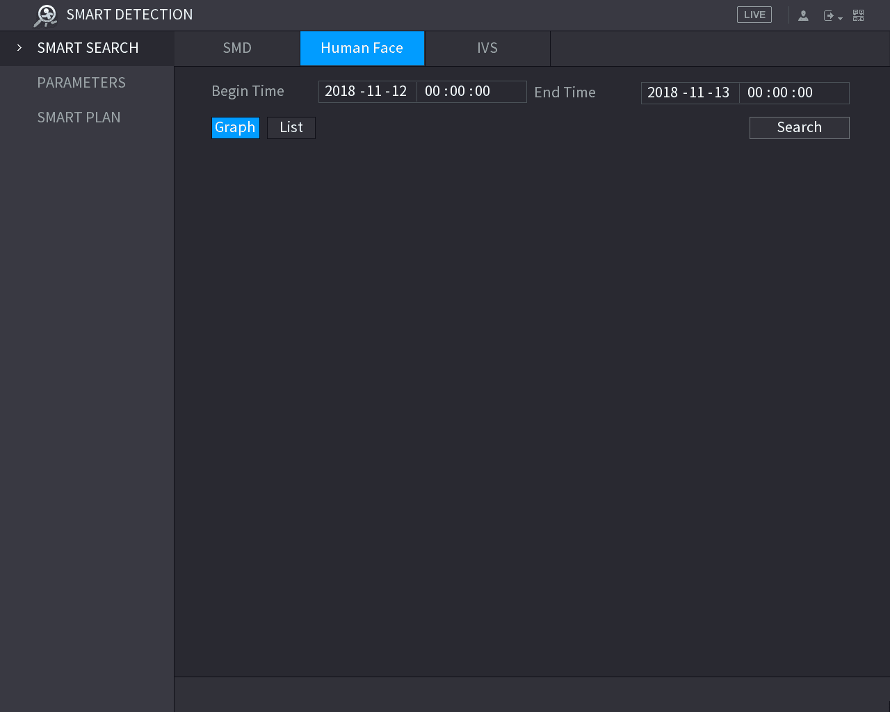
Enter the time
In the Begin Time box and End Time box, enter the time.
Select the display mode
Select the display by clicking Graph or clicking List.
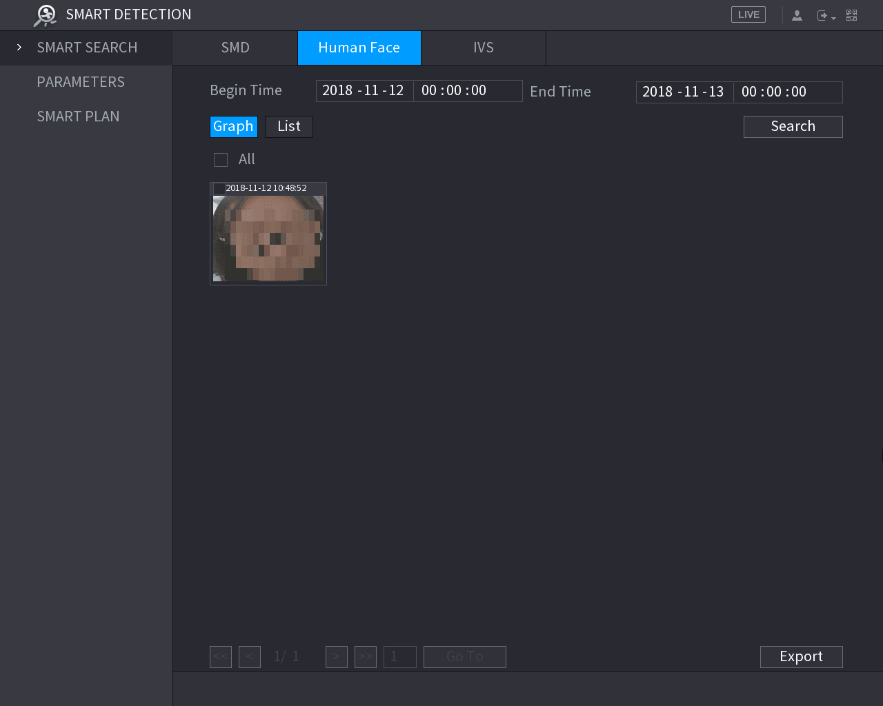
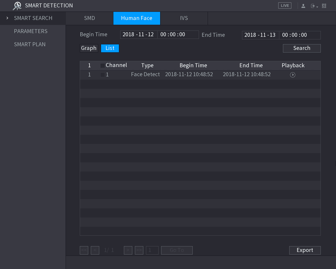
Export the results
Click Export to export the search results to the connected USB device.
Playing the Detected Faces
Open the VIDEO interface
On the displayed faces as shown in the graph view, double-click on the face.
The VIDEO interface is displayed.
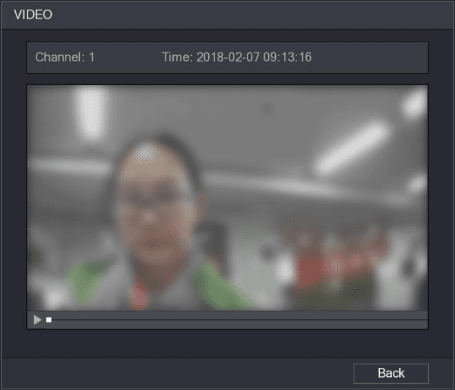
Play the detected face
Click the play icon to start playing the recorded detected face.
Return to the faces displaying interface
Click Back to exit the playing interface and return to the faces displaying interface.
Configuring IVS Function
The IVS function processes and analyzes the images to extract the key information to match with the preset rules. When the detected behaviors match with the rules, the system activates alarms.
The IVS function and face detection function cannot be enabled at the same time.
Configuring Intelligent Settings
You can configure the intelligent settings for both analog cameras and IP cameras.
- Not all models support this function.
- Please disable the expanded IP channels first before using this function for analog cameras.
Open the IVS interface
Select Main Menu > SMART DETECTION > PARAMETERS > IVS.
The IVS interface is displayed.
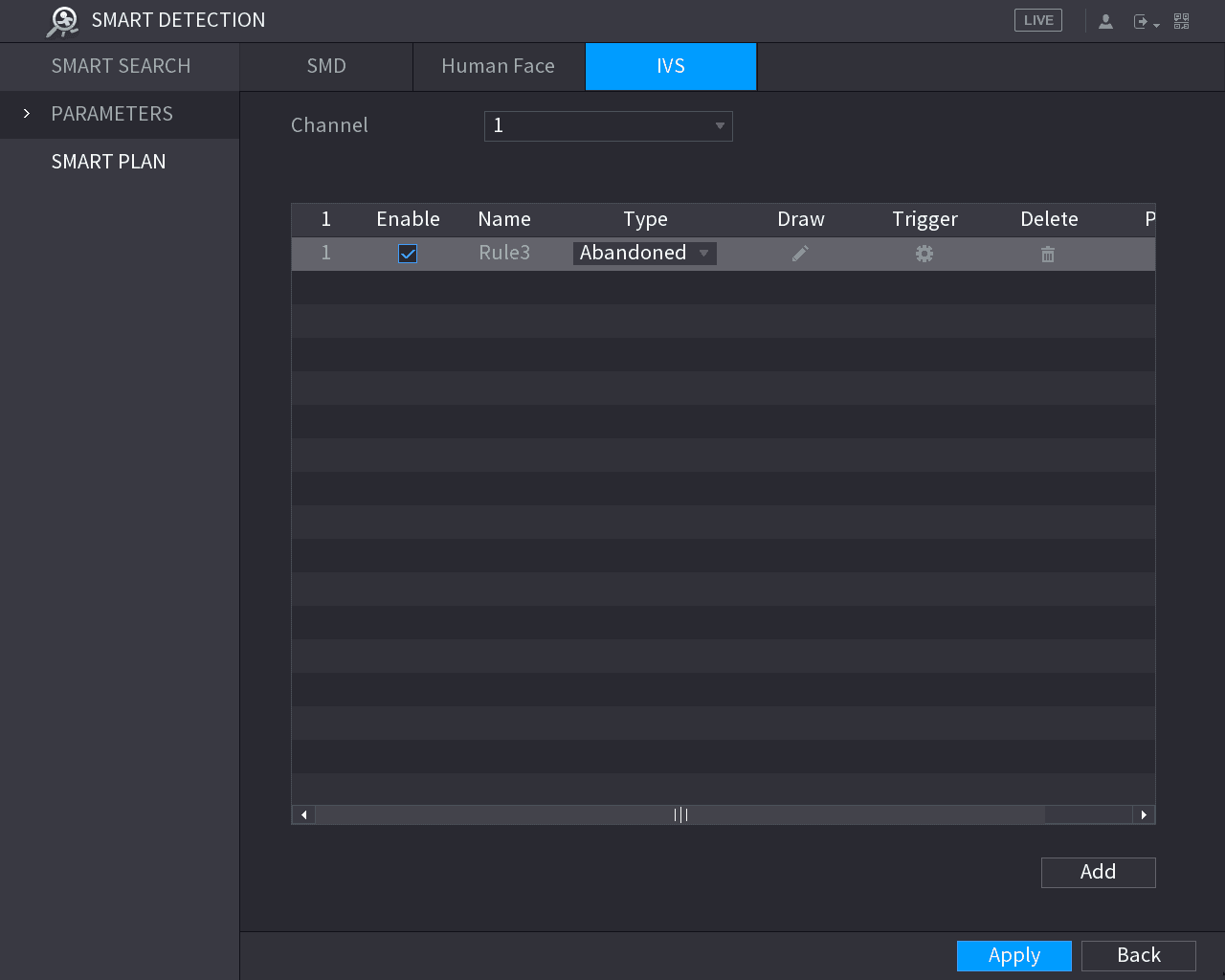
Select the channel
In the Channel list, select the channel number that you want to configure the IVS function.
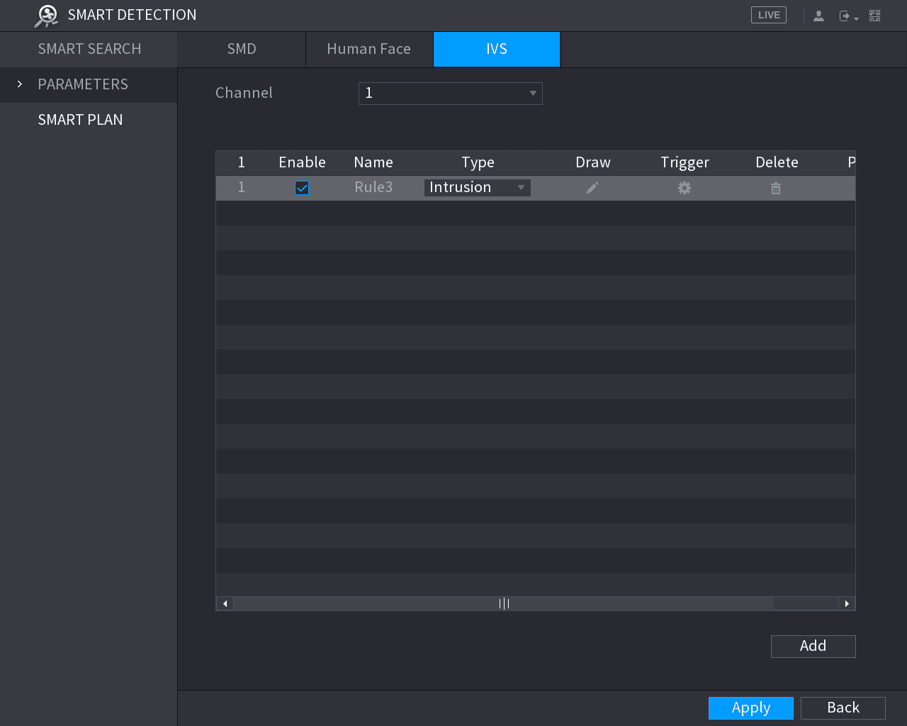
Configure the rule parameters
Configure the parameters for the rule that you selected.
Enable the rule
Select the check box of the rule to enable it.
Complete the settings
Click Apply to complete the settings.
Configuring Tripwire Rules
When the target object crosses the tripwire in the defined direction, the system activates alarms.
- The tripwire can be configured as a straight line or broken line.
- Supports detecting one-way or two-way tripwire crossing.
- Supports multiple tripwires in the same scenario to meet the complexity.
- Supports size filtering for target.
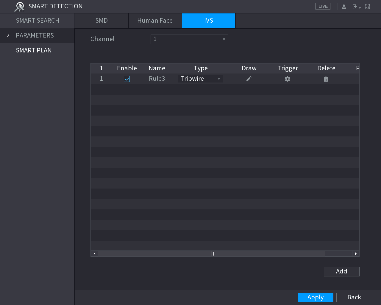
Draw a tripwire
In the Channel list, select the channel that you want to configure the rules for.
Click the draw icon.
The monitoring screen to configure the tripwire rules is displayed. See the following figure for analog camera and the IP camera without preset, and see the figure after it for IP camera with preset.
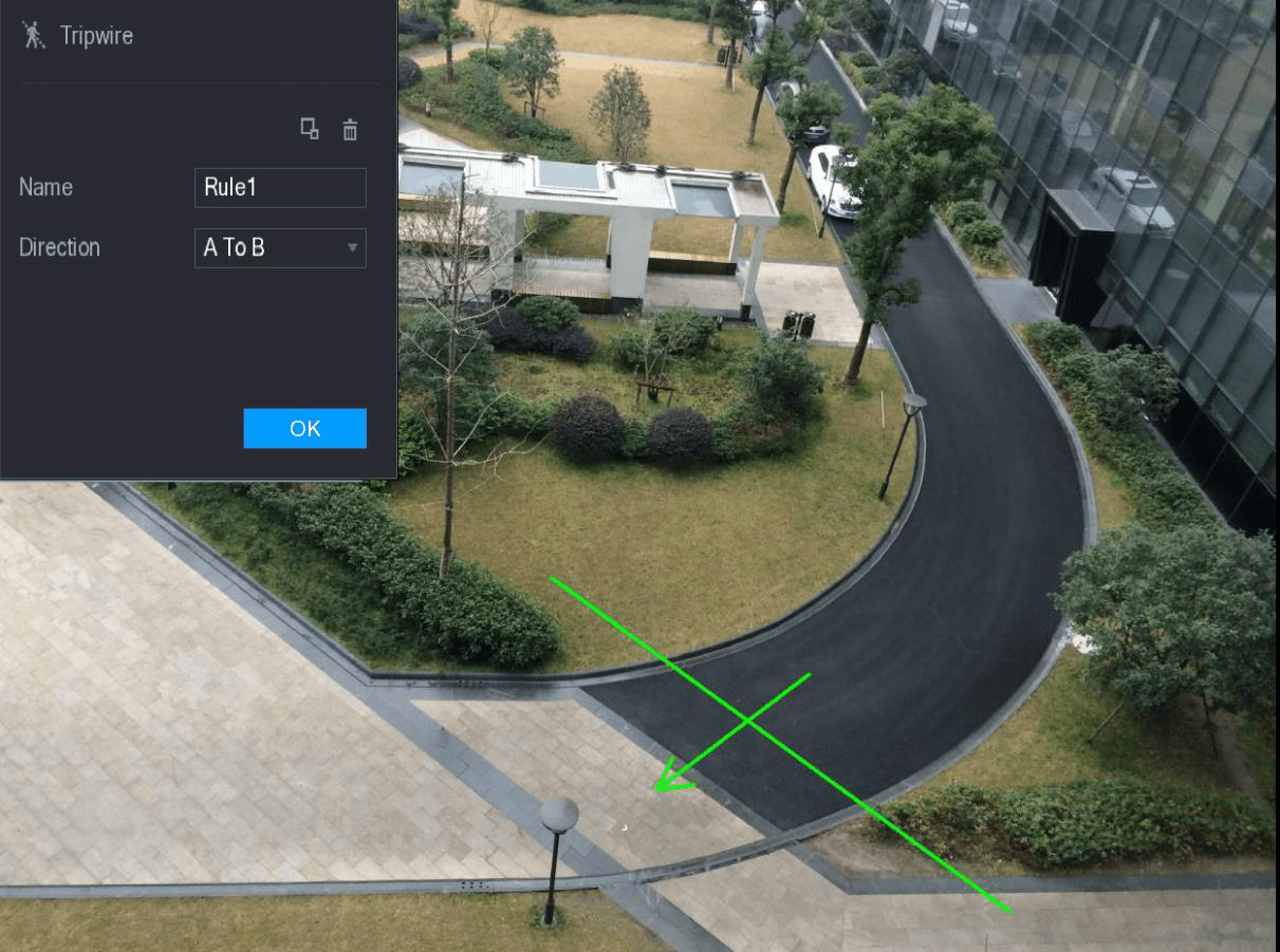
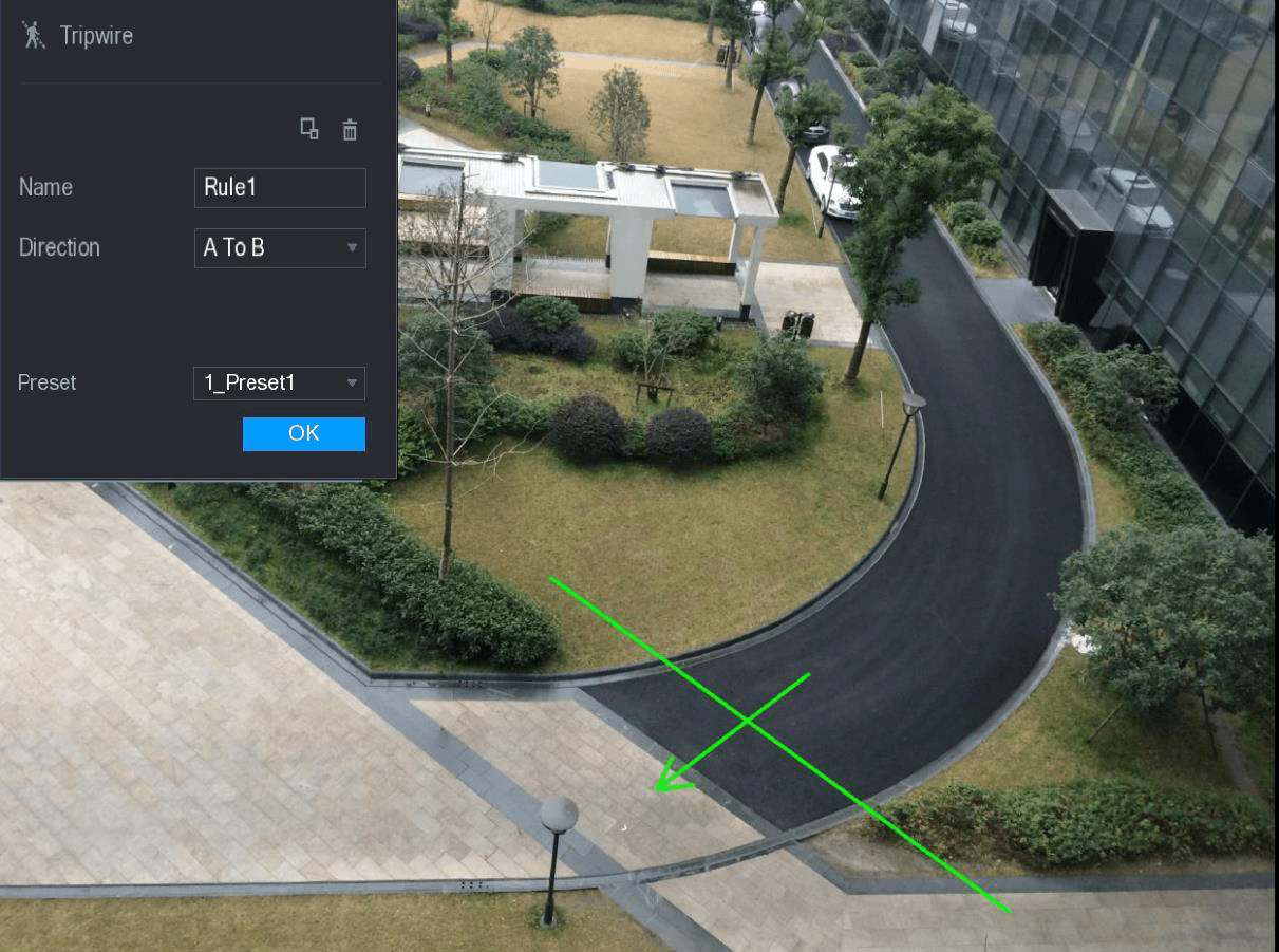
Configure the settings for the parameters of drawing rules.
| Parameter | Description |
|---|---|
| Name | Enter the customized rule name. |
| Direction | Set the direction of the tripwire. You can choose A to B (left to right), B to A (right to left), and Both. |
| Filtering Target | Click the filter icon to draw areas to filter the target. You can configure two filtering targets (maximum size and minimum size). When the target that is crossing the tripwire is smaller than the minimum size or larger than the maximum size, no alarms will be activated. The maximum size should be larger than the minimum size. |
| Preset | In the Preset list, select the preset that you want to configure the rule for. |
Drag to draw a tripwire. The tripwire can be a straight line, broken line or polygon.
Click OK to save the settings.
Set the triggered actions
Click the trigger icon to set the actions to be triggered.
The Trigger interface is displayed.
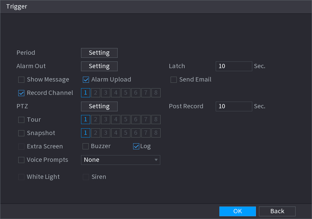
Configure the triggering parameters.
| Parameter | Description |
|---|---|
| Period | Click Setting to display set interface. Define a period during which the alarm linkage is active. For details, see "Setting Motion Detection Period" section in "5.10.4.1 Configuring Motion Detect Settings." |
| Alarm Out | Click Setting to display setting interface. - General Alarm: Enable alarm activation through the alarm devices connected to the selected output port. - External Alarm: Enable alarm activation through the connected alarm box. - Wireless Siren: Enable alarm activation through devices connected by USB gateway or camera gateway. |
| Latch | Set a length of time for the Device to delay turning off alarm after the external alarm is cancelled. The value ranges from 0 seconds to 300 seconds, and the default value is 10 seconds. |
| Show Message | Select the Show Message check box to enable a pop-up message in your local host PC. |
| Alarm Upload | Select the Alarm Upload check box to enable the system to upload the alarm signal to the network (including alarm center) when an alarm event occurs. |
| Send Email | Select the Send Email check box to enable the system to send an email notification when an alarm event occurs. To use this function, make sure the email function is enabled in Main Menu > NETWORK > EMAIL. |
| Record Channel | Select the channel(s) that you want to record. The selected channel(s) starts recording after an alarm event occurs. The recording for intelligence event and auto recording function must be enabled. For details, see "5.1.4.9 Configuring Recorded Video Storage Schedule" and "5.9.1 Enabling Record Control." |
| PTZ | Click Setting to display the PTZ interface. Enable PTZ linkage actions, such as selecting the preset that you want to be called when an alarm event occurs. |
| Post Record | Set a length of time for the Device to delay turning off recording after the alarm is cancelled. The value ranges from 10 seconds to 300 seconds. |
| Tour | Select the Tour check box and the channels to enable a tour of the selected channels when an alarm event occurs. |
| Snapshot | Select the Snapshot check box to take a snapshot of the selected channel when an alarm event occurs. To use this function, select Main Menu > CAMERA > ENCODE > Snapshot, in the Mode list, select Event. |
| Extra Screen | Select the check box to enable the function. When an alarm event occurs, the extra screen outputs the settings configured in Main Menu > DISPLAY > TOUR > Extra Screen. - Not all models support this function. - To use this function, extra screen shall be enabled. |
| Video Matrix | Select the check box to enable the function. When an alarm event occurs, the video output port outputs the settings configured in "Main Menu > Display > Tour." Not all models support this function. |
| Buzzer | Select the check box to activate a buzzer noise at the Device when an alarm event occurs. |
| Log | Select the check box to enable the Device to record a local alarm log when an alarm event occurs. |
| Voice Prompts | Select the check box to enable audio broadcast in response to an alarm event. |
| White Light | Select the check box to activate a white light camera to trigger white light alarm. |
| Siren | Select the check box to activate an audio camera to trigger audio alert. |
Click OK to save the settings.
Enable the tripwire detection
The INTELL SETTING interface is displayed.
Select the Enable check box, and then click Apply.
The tripwire detecting function is active. When the target object crosses the tripwire in the defined direction, the system activates alarms.
Configuring Intrusion Rules
When the target enters and leaves the defined detection area, or the target appears in the defined area, the system activates alarms.
- You can define the shape and quantity of intrusion areas.
- Supports detecting the behaviors that enter and leave the intrusion areas.
- Supports detecting the behaviors that are moving in the intrusion areas. The quantity of areas and lasting time can be configured.
- Supports size filtering for target.
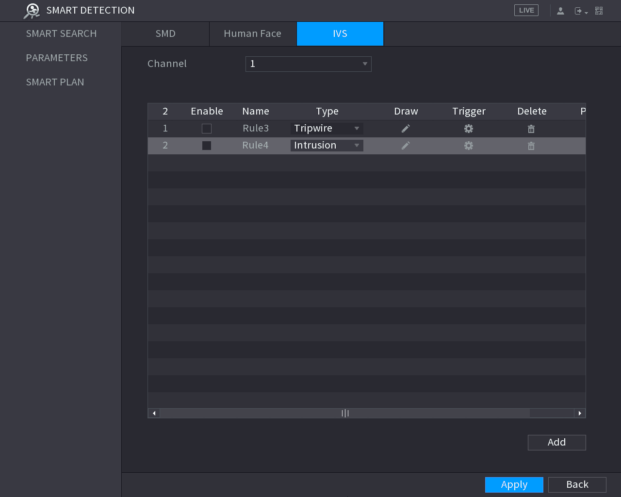
Draw an area
In the Channel list, select the channel that you want to configure the rules for.
Click the draw icon.
The monitoring screen to configure the intrusion rules is displayed. See the following figure for analog camera and the IP camera without preset, and see the figure after it for IP camera with preset.
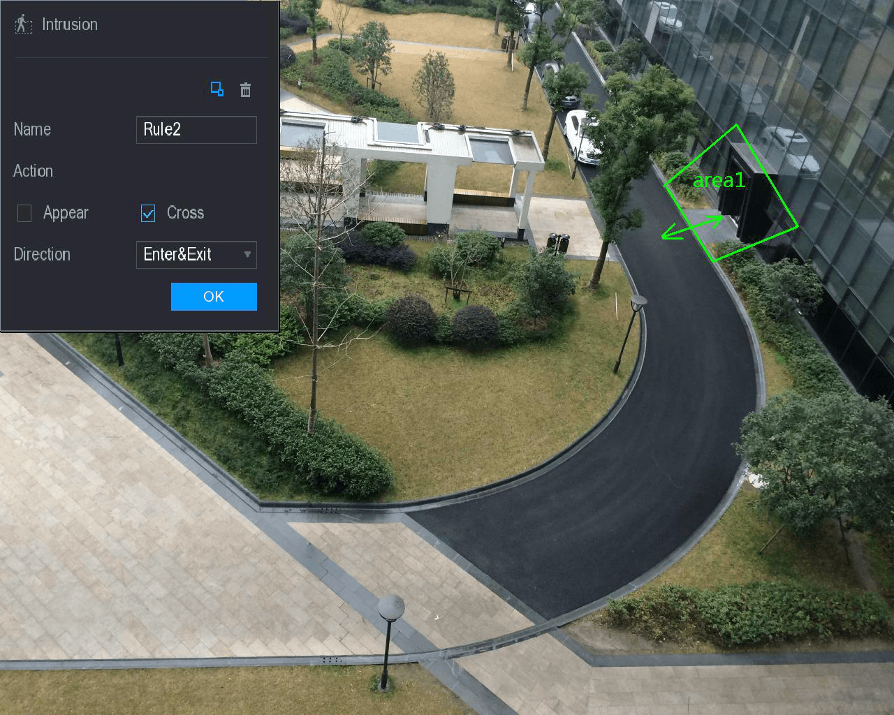
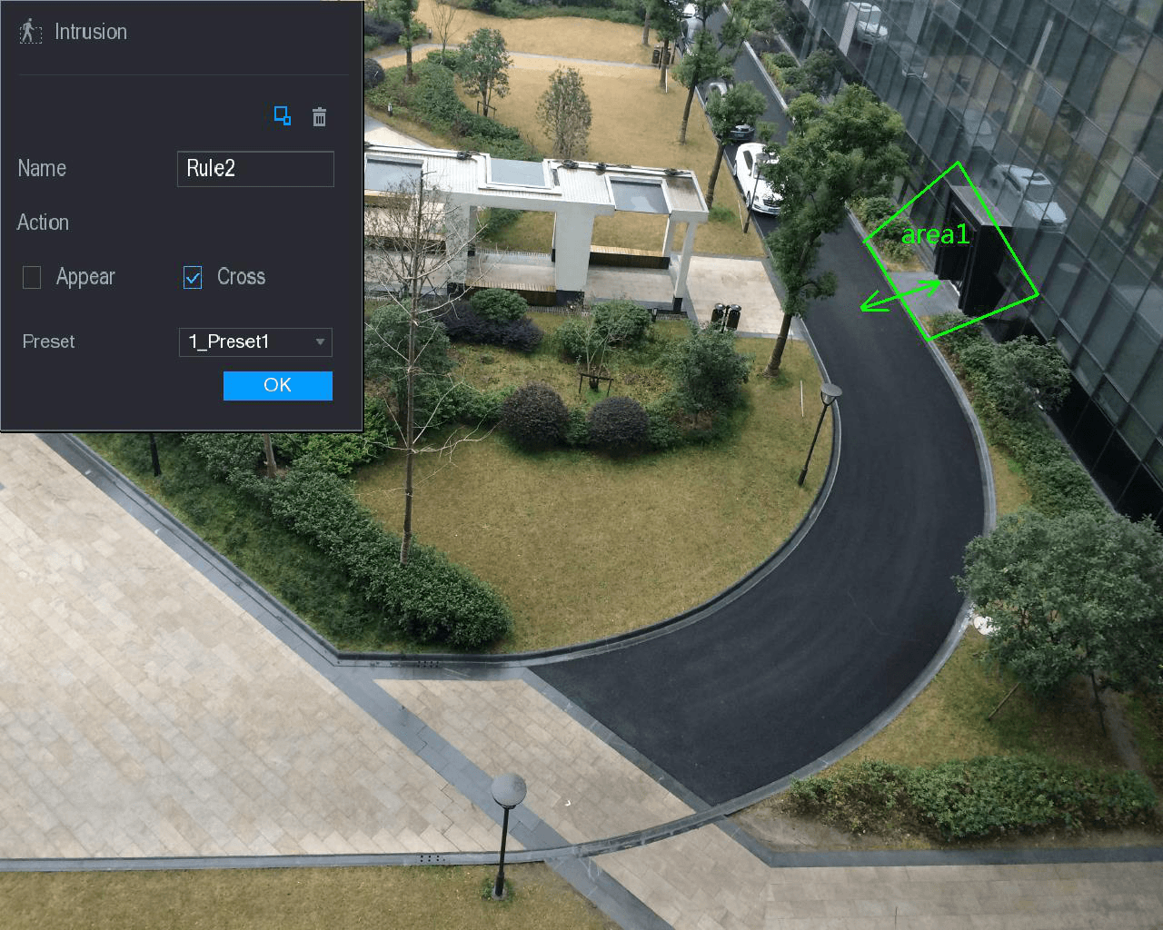
Configure the settings for the parameters of drawing rules.
| Parameter | Description |
|---|---|
| Name | Enter the customized rule name. |
| Action | Configure the actions that are defined as intrusion. You can select the Appear check box and the Cross check box. |
| Direction | In the Direction list, select the direction of crossing the configured area. You can select Enter&Exit, Enters, and Exits. |
| Filtering Target | Click the filter icon to draw areas to filter the target. You can configure two filtering targets (maximum size and minimum size). When the target that is crossing the tripwire is smaller than the minimum size or larger than the maximum size, no alarms will be activated. The maximum size should be larger than the minimum size. |
| Preset | In the Preset list, select the preset that you want to configure the rule for. |
Drag to draw an area.
Click OK to save the settings.
Set the triggered actions
Click the trigger icon to set the actions to be triggered. For details, see "Configuring Tripwire Rules."
Enable the intrusion detection
Select the Enable check box, and then click Apply.
The intrusion detecting function is active. When the target enters and leaves the area, or the target appears in the defined area, the system activates alarms.
Configuring Abandoned Rules
When the object is placed in the defined detection area for more than the set time, the system activates alarms.
- You can define the shape and quantity of detecting areas.
- Period value can be configured.
- Supports size filtering for target.
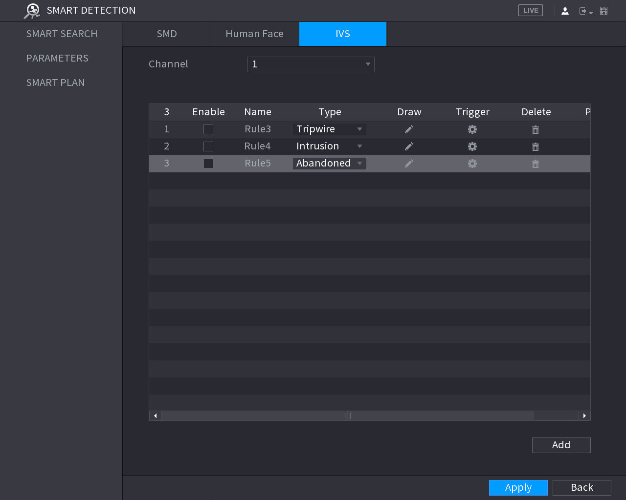
Draw an area
In the Channel list, select the channel that you want to configure the rules for.
Click the draw icon.
The monitoring screen to configure the abandoned rules is displayed. See the following figure for analog camera and see the figure after it for IP camera.
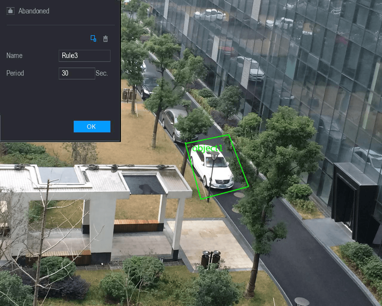
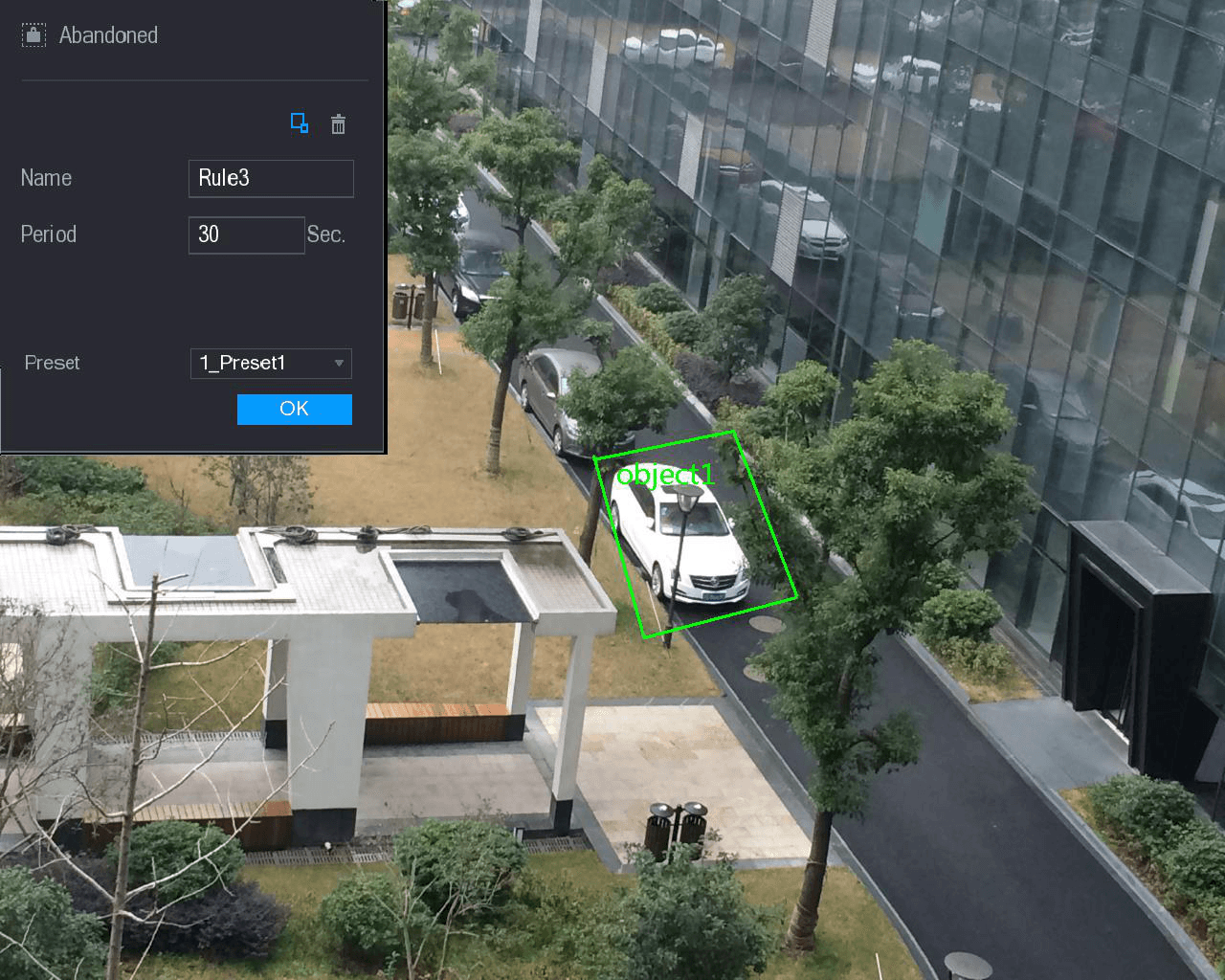
Configure the settings for the parameters of drawing rules.
| Parameter | Description |
|---|---|
| Name | Enter the customized rule name. |
| Period | Configure the minimum time period for activating alarms by detecting the abandoned objects. |
| Filtering Target | Click the filter icon to draw areas to filter the target. You can configure two filtering targets (maximum size and minimum size). When the target that is crossing the tripwire is smaller than the minimum size or larger than the maximum size, no alarms will be activated. The maximum size should be larger than the minimum size. |
| Preset | In the Preset list, select the preset that you want to configure the rule for. |
Drag to draw an area.
Click OK to save the settings.
Set the triggered actions
Click the trigger icon to set the actions to be triggered. For details, see "Configuring Tripwire Rules."
Enable the abandoned object detection
Select the Enable check box, and then click Apply.
The abandoned object detecting function is active.
Configuring Missing Rules
When the target is taken away from the defined detection area exceeds the set time, the system activates alarms.
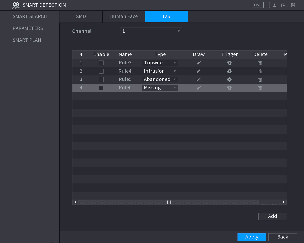
Draw an area
In the Channel list, select the channel that you want to configure the rules for.
Click the draw icon.
The monitoring screen to configure the missing rules is displayed. See the following figure for analog camera and the IP camera without preset, and see the figure after it for IP camera with preset.
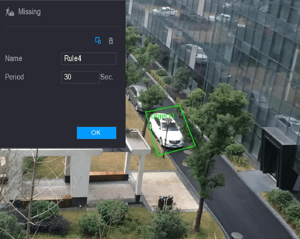
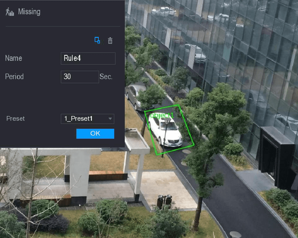
Configure the settings for the parameters of drawing rules.
| Parameter | Description |
|---|---|
| Name | Enter the customized rule name. |
| Period | Configure the minimum time period for activating alarms by detecting the missing objects. |
| Filtering Target | Click the filter icon to draw areas to filter the target. You can configure two filtering targets (maximum size and minimum size). When the target that is crossing the tripwire is smaller than the minimum size or larger than the maximum size, no alarms will be activated. The maximum size should be larger than the minimum size. |
| Preset | In the Preset list, select the preset that you want to configure the rule for. |
Drag to draw an area.
Click OK to save the settings.
Set the triggered actions
Click the trigger icon to set the actions to be triggered. For details, see "Configuring Tripwire Rules."
Enable the missing object detection
Select the Enable check box, and then click Apply.
The missing object detecting function is active. When the target is taken away from the defined area exceeds the set time, the system activates alarms.
Enabling the Intelligent Settings for IP Camera
- Not all IP cameras support this function.
- The interface might be different depending on the connected IP camera.
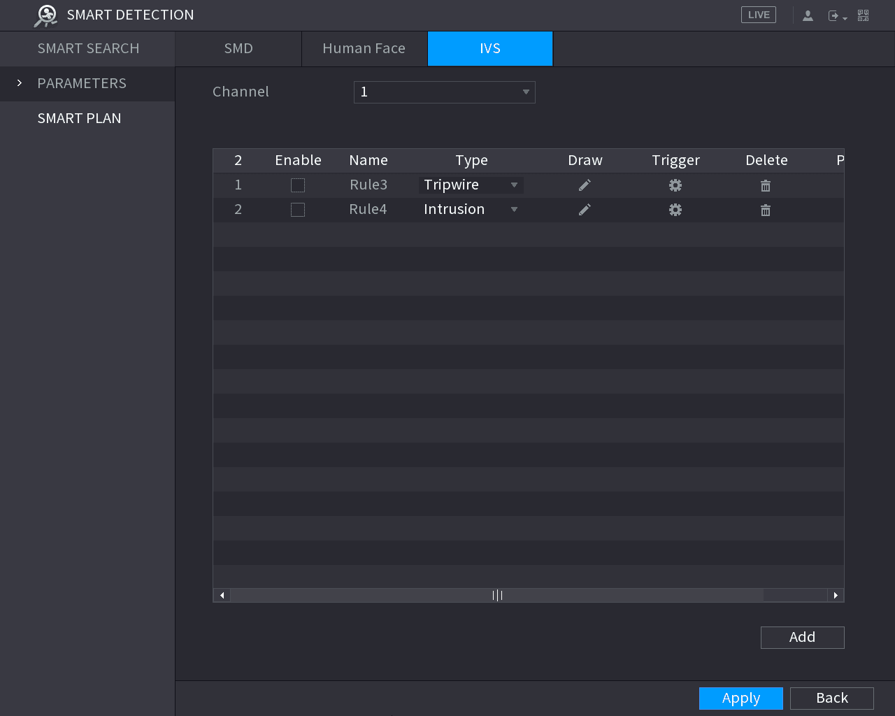
After configuring the intelligent settings for IP cameras (refer to "Configuring Intelligent Settings"), you still need to enable to apply the configurations. For example, you have configured the intelligent settings for IP camera as displayed in the following figure, and then click Apply to save the settings.
Select the IP camera channel
In the Channel list, select the IP camera channel that you have configured the intelligent settings.
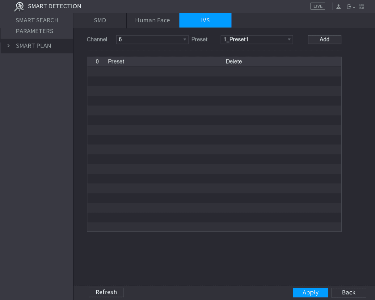
For the IP camera with preset, see the following figure.
The IP camera with preset means the speed dome. The displayed preset information has been configured before on the speed dome from front-end intelligence settings.
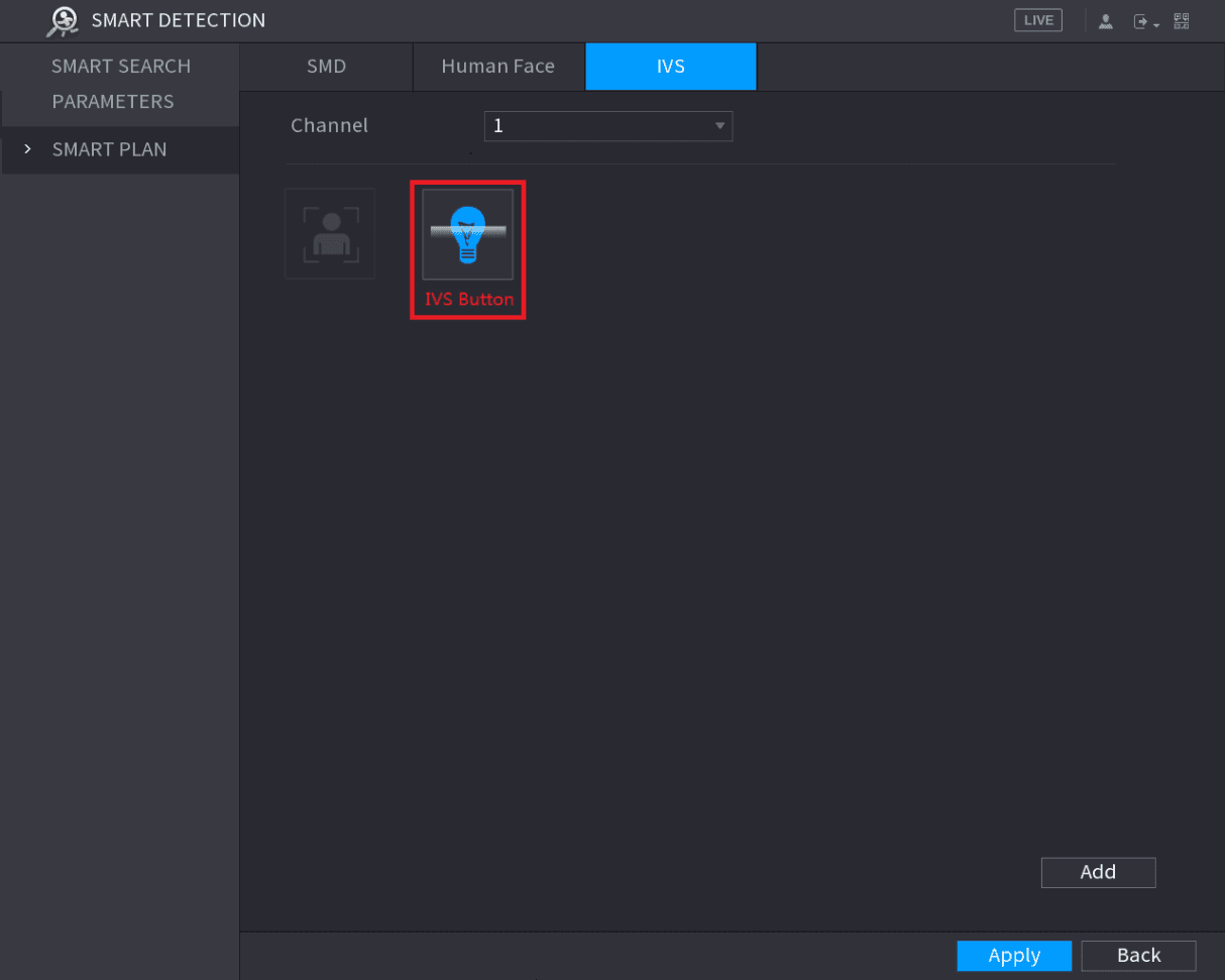
For the IP camera without preset, see the following figure.
Enable the IVS function
For the IP camera with preset, do the following:
In the Preset list, select 1_Preset1.
All the presets that the IP camera has are displayed in the Preset list, and you just need to select the preset that you have configured the intelligent settings as shown in the IVS settings figure above.
Click Add.
The selected preset is displayed in the table and the IVS button and Face Detect button are displayed.
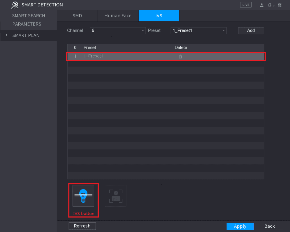
Select the line of 1_Preset1.
Click IVS button to enable the intelligent settings to preset 1. The buttons is displayed in blue.
Click Apply to complete the settings.
For the IP camera without preset, click the IVS button and then click Apply to complete the settings.
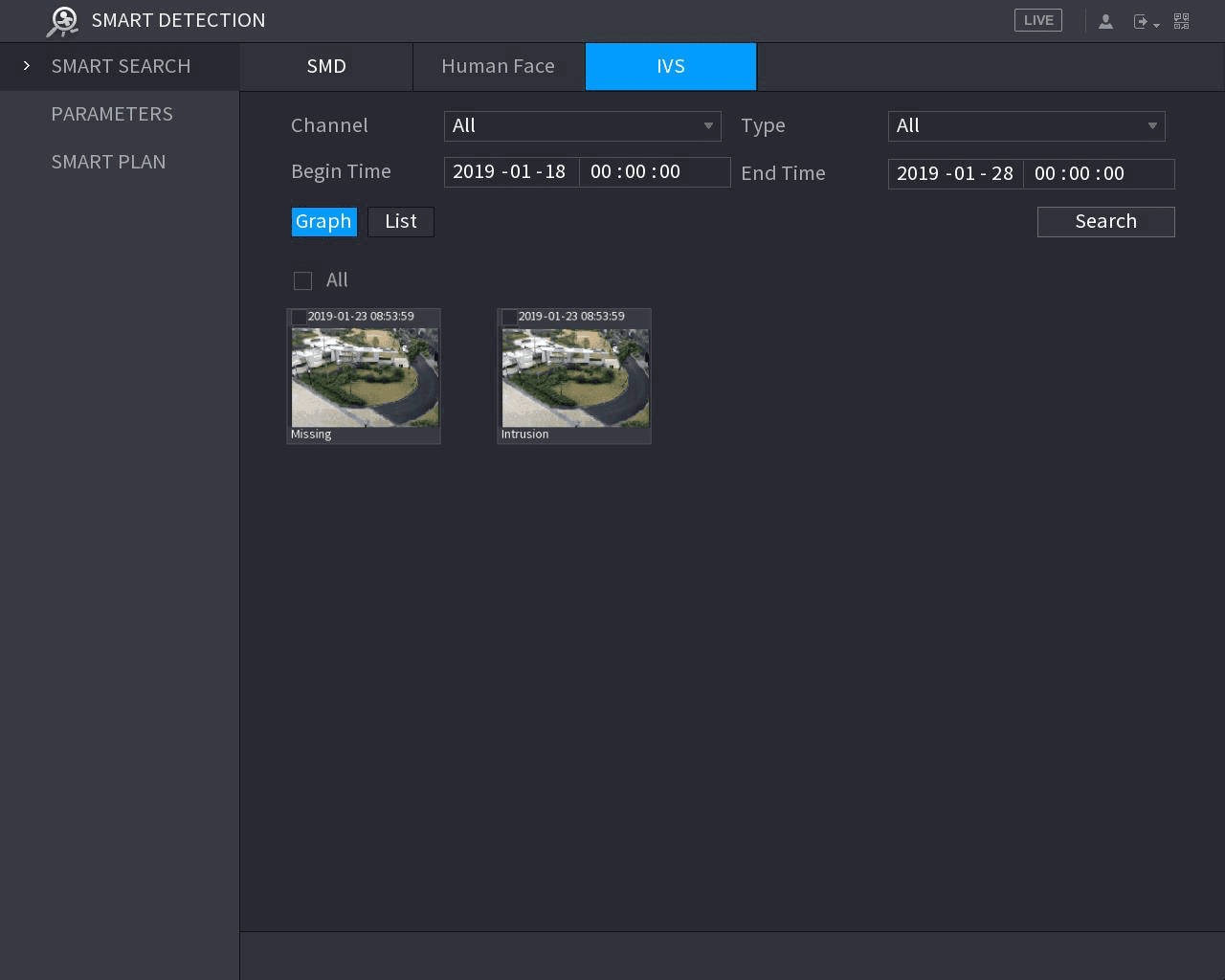
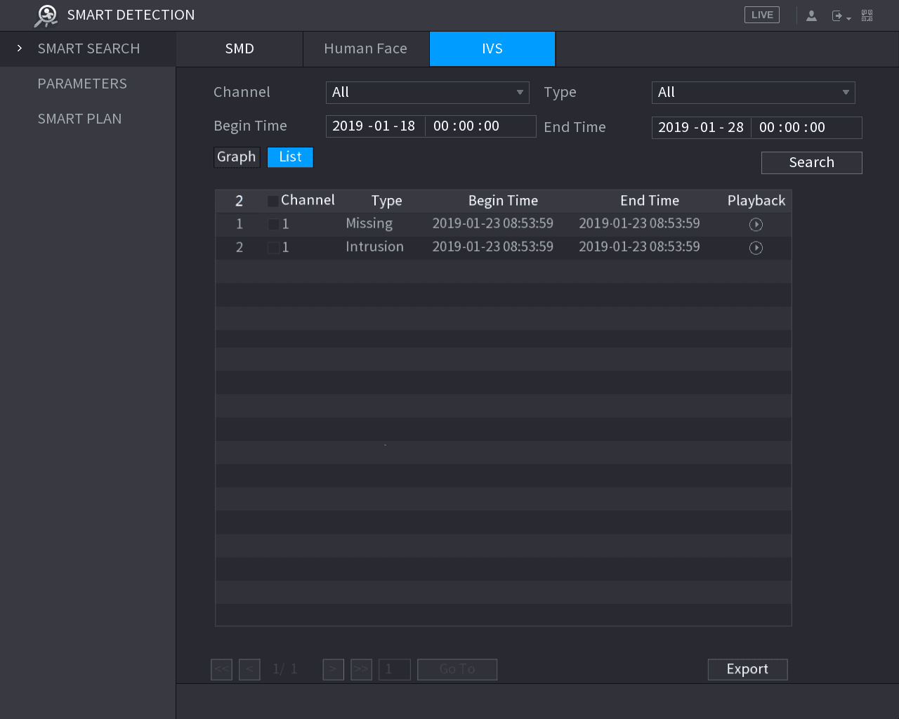
Using Smart Search
You can search for the intelligent events and display in graph or list.
Open the SMART SEARCH interface
Select Main Menu > SMART DETECTION > SMART SEARCH.
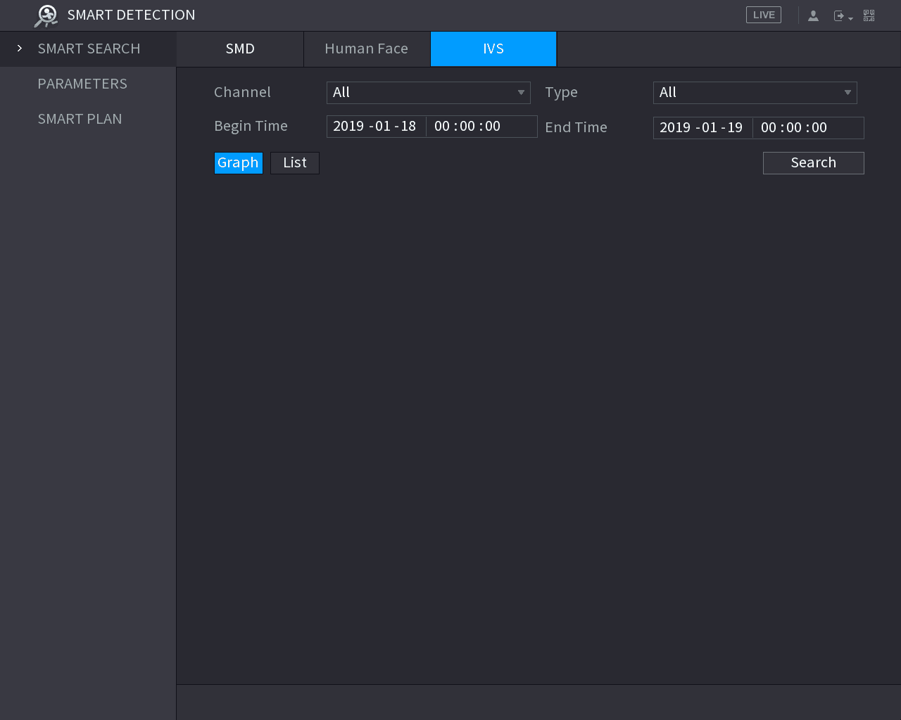
The SMART SEARCH interface is displayed.
Set the search conditions
In the Channel list, select the channel that you want to search for the events.
In the Type list, select the event type that you want to search.
In the Begin Time box and End Time box, enter the date and time.
Select the display mode of the search results by clicking Graph or List.
Play back an event
Double-click the video or click the play icon.
Alarm Events Settings
Configure alarm information, alarm input and output, video detection, and system event alarms on the Sapphire Series CVI DVR.
IoT Function
Pair wireless sensors, configure temperature and humidity cameras, and set up wireless sirens with alarm linkage on the Sapphire Series CVI DVR.