 LTS Connect hjelpesenter
IoT Function
Pair wireless sensors, configure temperature and humidity cameras, and set up wireless sirens with alarm linkage on the Sapphire Series CVI DVR.
Configuring Sensor Settings
You can connect external sensors wirelessly through the Device with USB gateway or through connecting to a camera gateway. After connection, you can activate alarm events through external sensors.
Connecting Sensor through Device
Only the Device with USB gateway supports this function.
Open Sensor Pairing
Select Main Menu > IoT > MANAGER > Sensor Pairing.
The Sensor Pairing interface is displayed. See Figure 5-170.
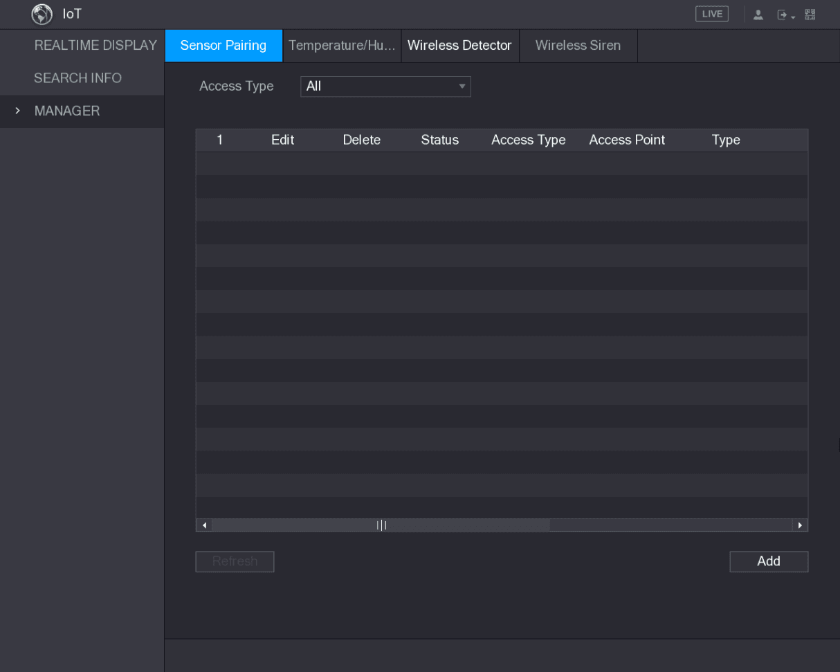
Select the access type
In the Access Type list, select USB Gateway.
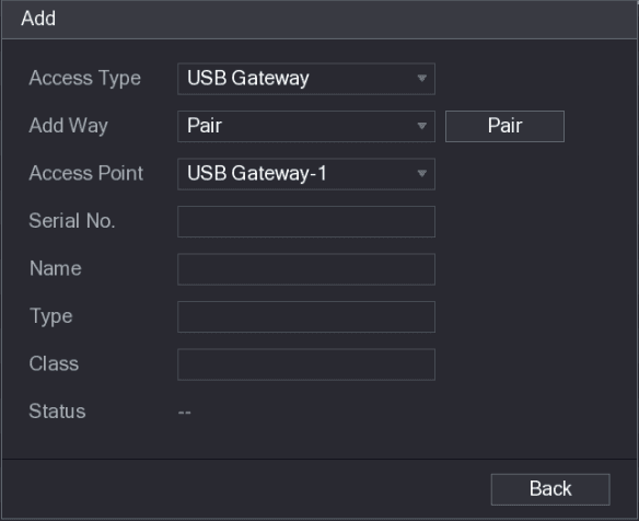
Pair the sensor
Click Pair.
The Device starts pairing with the sensor.
After pairing is completed, see Figure 5-172.
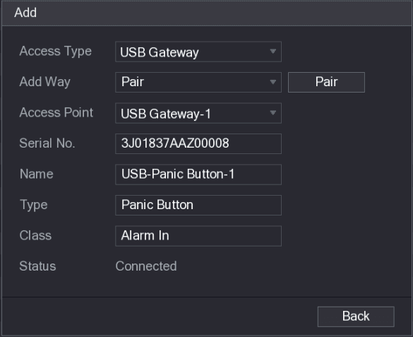
Exit the pairing interface
Click Back to exit the pairing interface.
The added sensor information is displayed. See Figure 5-173.
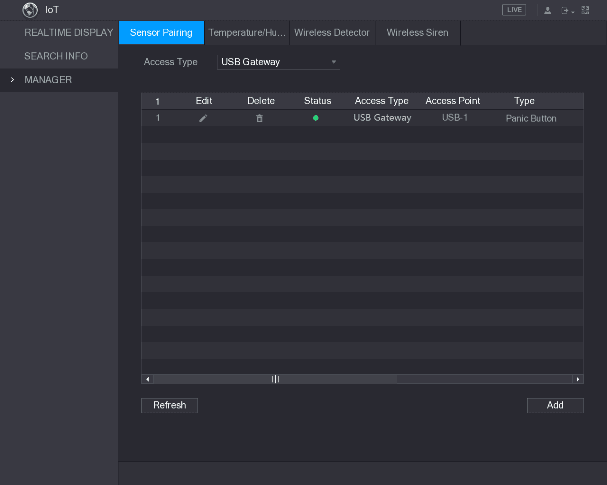
Click the edit icon to modify the sensor name; click the delete icon to delete sensor information.
Connecting Sensor through Camera with Gateway
Only the camera with gateway supports this function.
Open Sensor Pairing
Select Main Menu > IoT > MANAGER > Sensor Pairing.
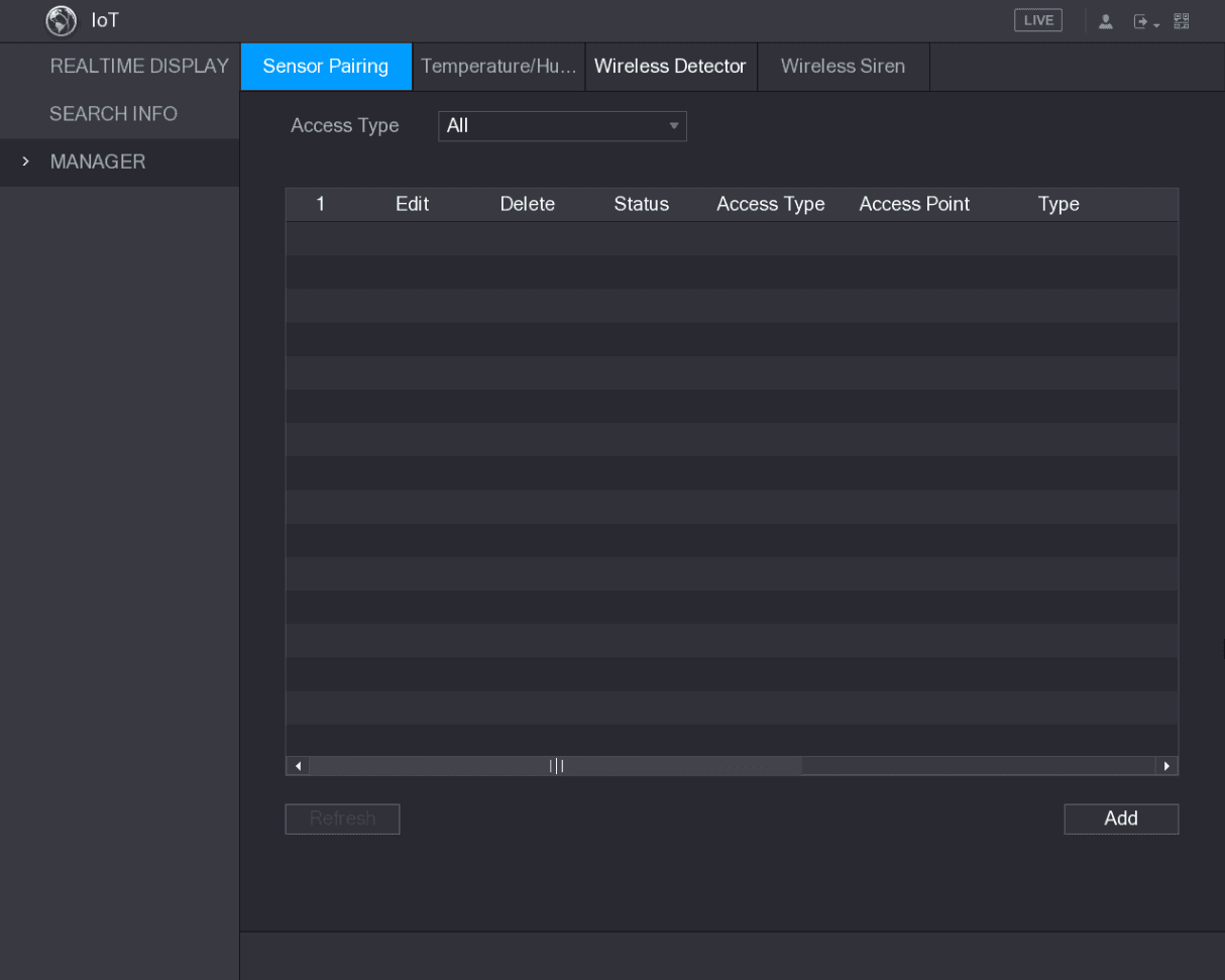
The Sensor Pairing interface is displayed. See Figure 5-174.
Select the access type and channel
In the Access Type list, select Camera Gateway.
In the Channel list, select the channel that is connected to the camera.
Pair the sensor
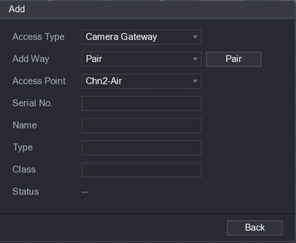
Click Pair.
The Device starts pairing with the sensor.
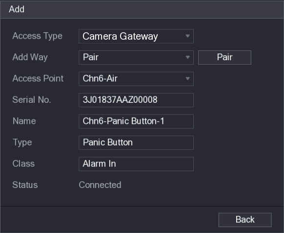
After pairing is completed, see Figure 5-176.
Exit the pairing interface
Click Back to exit the pairing interface.
The added sensor information is displayed. See Figure 5-177.
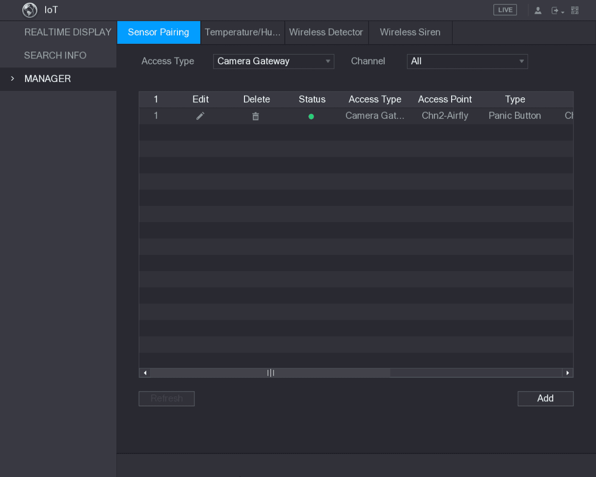
Click the edit icon to modify the sensor name; click the delete icon to delete sensor information.
Configuring Alarm Linkage
Open Wireless Detector
Select Main Menu > IoT > MANAGER > Wireless Detector.
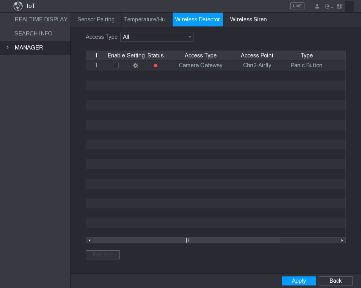
The Wireless Detector interface is displayed. See Figure 5-178.
Select the access type
In the Access Type list, select USB Gateway, Camera Gateway, or All.
When Access Type is Camera Gateway, you can select Channel to filter the status of present wireless detector.
Open the Setting interface
Click the Setting icon.
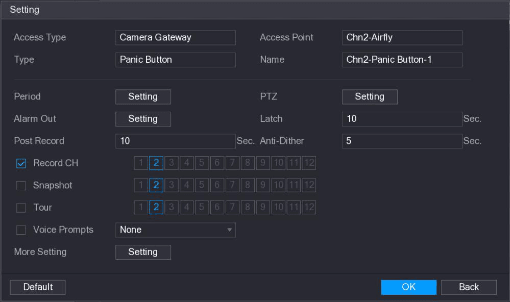
The Setting interface is displayed. See Figure 5-179.
Configure alarm linkage
Configure the settings for alarm linkage. For details, see Table 5-52.
| Parameter | Description |
|---|---|
| Name | Enter the customized alarm name. |
| Period | Click Setting to display setting interface. Define a period during which the motion detection is active. For details, see "Setting Motion Detection Period" section in "5.10.4.1 Configuring Motion Detect Settings." |
| PTZ | Click Setting to display the PTZ interface. Enable PTZ linkage actions, such as selecting the preset that you want to be called when an alarm event occurs. |
| Alarm Out | Click Setting to display setting interface. General Alarm: Enable alarm activation through the alarm devices connected to the selected output port. External Alarm: Enable alarm activation through the connected alarm box. Wireless Siren: Enable alarm activation through devices connected by USB gateway or camera gateway. |
| Latch | Set a length of time for the Device to delay turning off alarm after the external alarm is cancelled. The value ranges from 0 seconds to 300 seconds, and the default value is 10 seconds. |
| Post Record | Set a length of time for the Device to delay turning off recording after the alarm is cancelled. The value ranges from 10 seconds to 300 seconds, and the default value is 10 seconds. |
| Anti-Dither | Configure the time period from end of event detection to the stop of alarm. |
| Record Channel | Select the channel(s) that you want to record. The selected channel(s) starts recording after an alarm event occurs. The recording for alarm and auto recording must be enabled. For details, see "5.1.4.9 Configuring Recorded Video Storage Schedule" and "5.9.1 Enabling Record Control." |
| Snapshot | Select the Snapshot check box to take a snapshot of the selected channel. To use this function, select Main Menu > CAMERA > ENCODE > Snapshot, in the Mode list, select Event. |
| Tour | Select the Tour check box to enable a tour of the selected channels. |
| Voice Prompts | Select to enable audio broadcast/voice prompts in response to a local alarm event. |
| More Setting | Show Message: Select the Show Message check box to enable a pop-up message in your local host PC. Buzzer: Select the check box to activate a buzzer noise at the Device. Video Matrix: Select the check box to enable the function. When an alarm event occurs, the video output port outputs the settings configured in "Main Menu > DISPLAY > TOUR." (Not all models support this function.) Send Email: Enable the system to send an email notification when an alarm event occurs. To use this function, make sure the email function is enabled in Main Menu > NETWORK > EMAIL. Log: Select the check box to enable the Device to record a local alarm log. Extra screen: Select the check box to enable the function. When an alarm event occurs, the extra screen outputs the settings configured in Main Menu > DISPLAY > TOUR > Extra Screen. (Not all models support this function. To use this function, extra screen shall be enabled.) |
Save the settings
Click OK to save the settings.
On the Wireless Detector interface, click Apply to complete the settings.
Configuring Temperature and Humidity Camera
You can view, search and export the temperature and humidity data of camera with such sensors and configure the alarm event settings.
To use this function, please make sure there is at least one camera with temperature and humidity sensor has been connected to the Device.
Enabling Detecting Function
You should enable the IoT function the first time when you enter this interface.
Open Temperature/Humidity
On the main menu, select IoT > MANAGER > Temperature/Humidity.
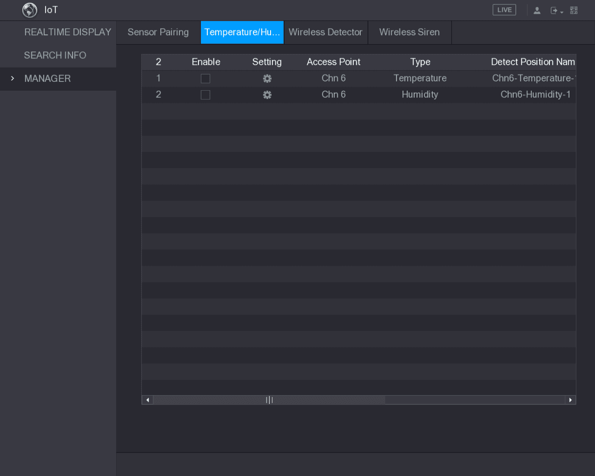
The Temperature/Humidity interface is displayed. See Figure 5-180.
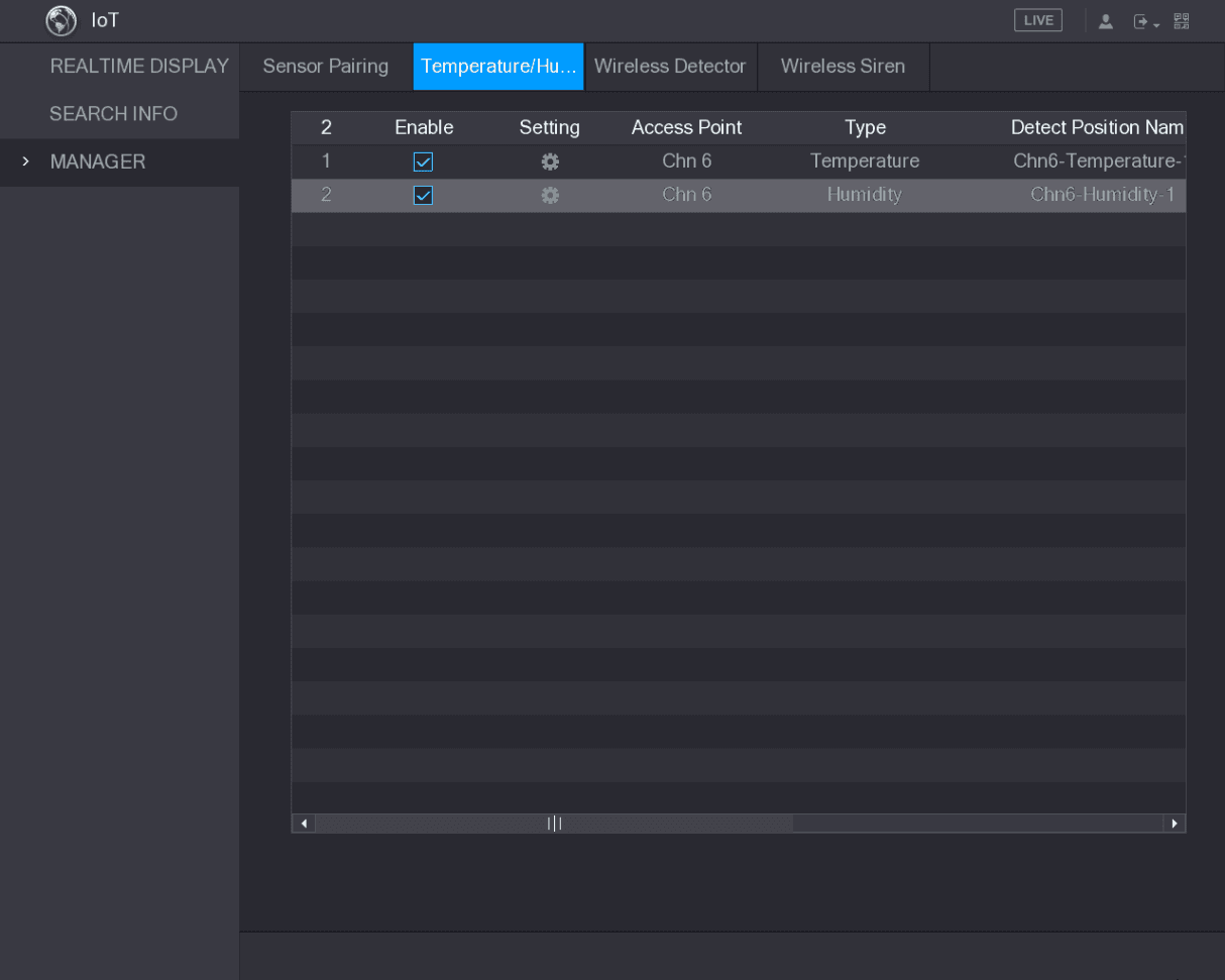
The Device starts detecting the temperature and humidity data from the camera and display on the Realtime Display interface.
Viewing Temperature and Humidity Data
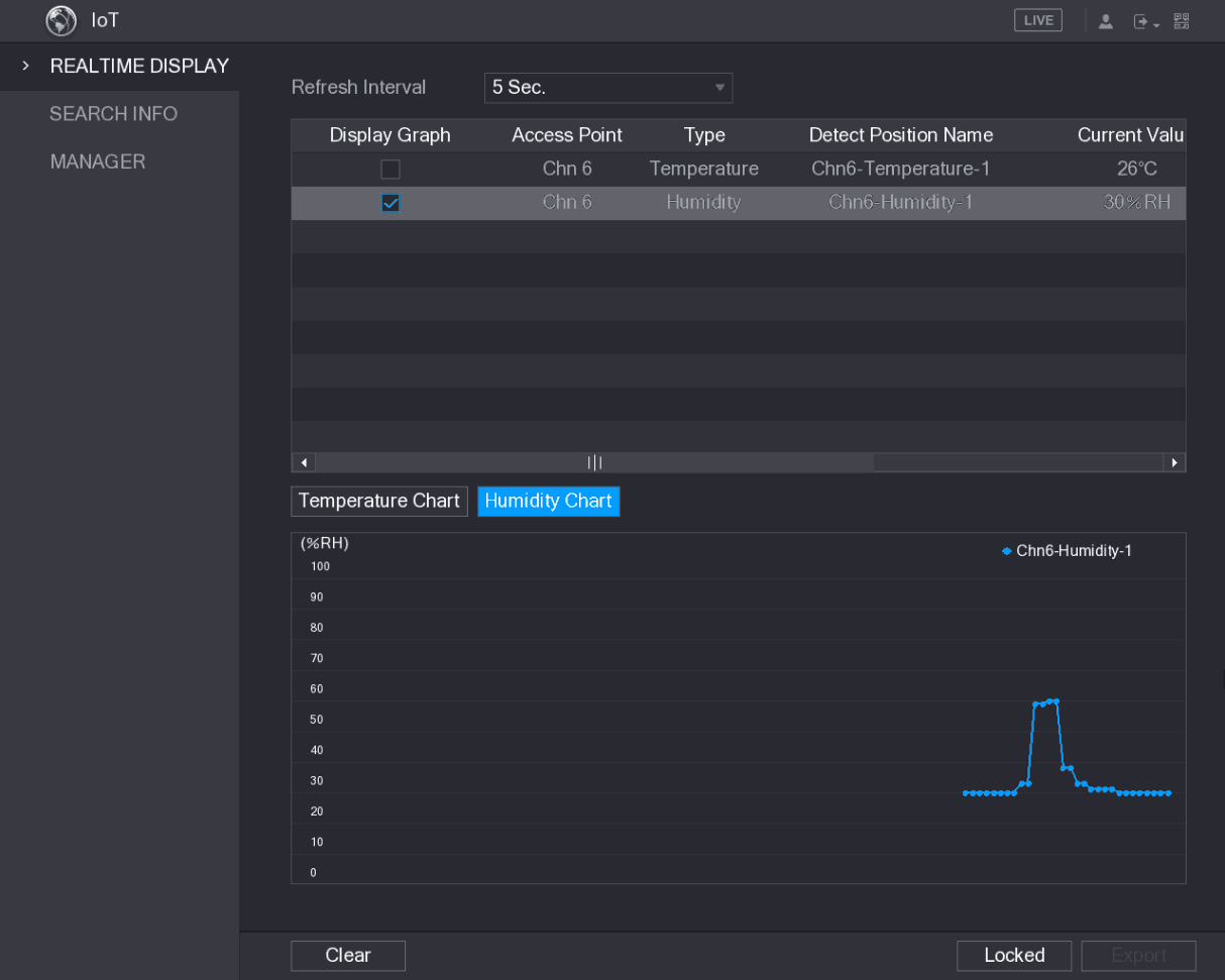
You can view the temperature and humidity data on the REALTIME DISPLAY interface after the IoT function is enabled.
In the Refresh Interval box, select data refresh interval. For example, you can select 5 Sec.
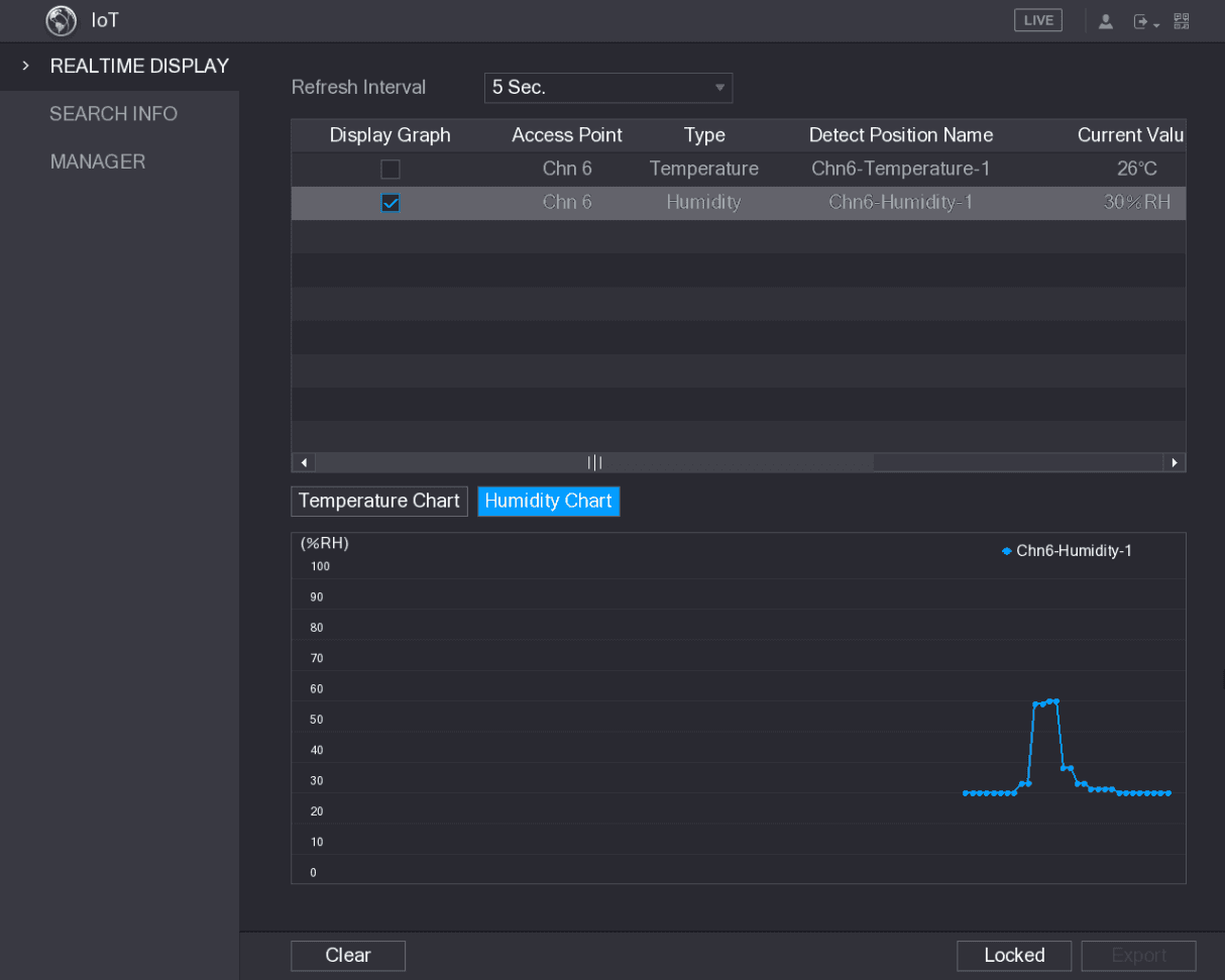
You can also display the temperature and humidity data in graphical way by selecting the Display Graph check box to. See Figure 5-182 for humidity data in graphical way.
Click Clear to delete the data.
Exporting Temperature and Humidity Data
You can export the temperature and humidity data in .BMP format. Take exporting humidity data as an example.
Plug in a USB device
Prepare a USB device and plug it into the Device.
Export the data
Click Export. The system starts exporting the data.
After exporting is finished, a Message dialog box is displayed.
Configuring Alarm Linkage
You can configure alarm linkage settings for temperature and humidity data.
Configuring Alarm Linkage for Temperature Data
Open Temperature/Humidity
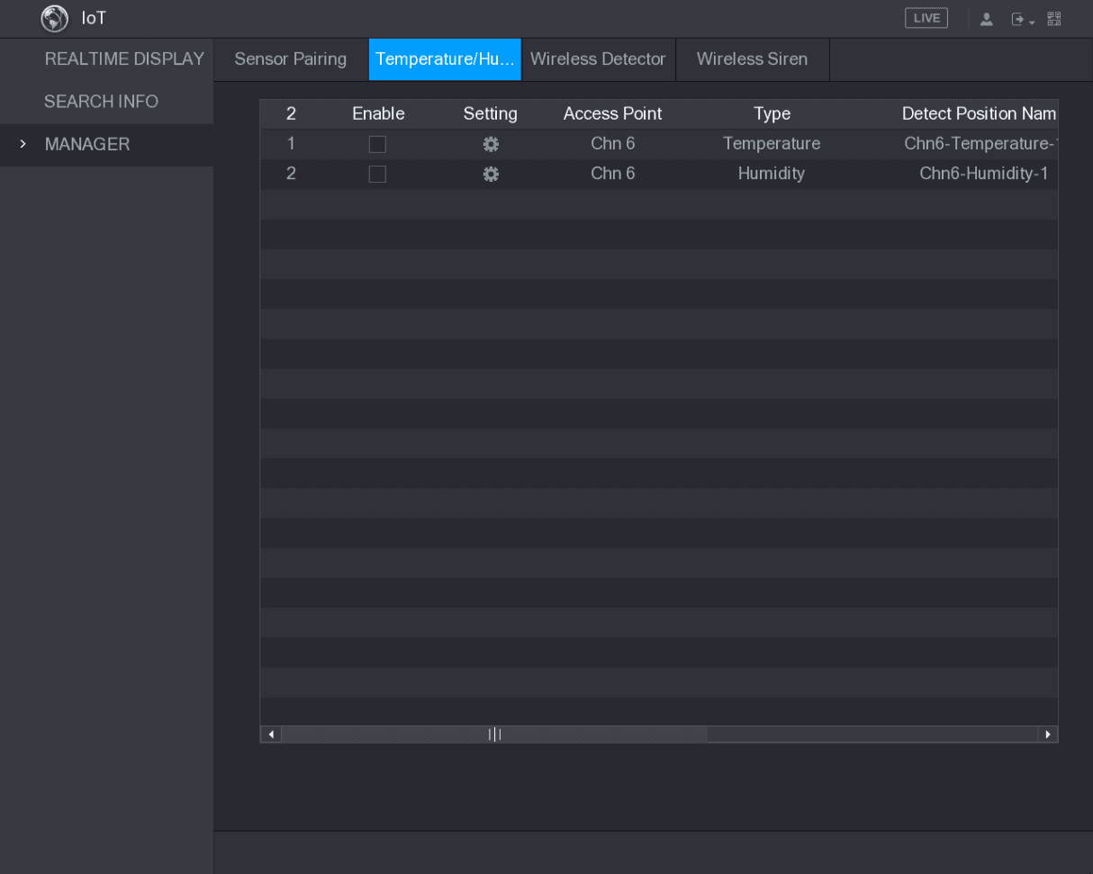
On the main interface, select IoT > MANAGER > Temperature/Humidity.
The Temperature/Humidity interface is displayed. See Figure 5-184.
Open the Setting interface
On the temperature information line, click the Setting icon.
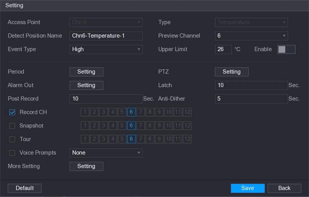
The Setting interface is displayed. See Figure 5-185.
Configure the settings
Configure the settings for alarm linkage. See Table 5-53.
| Parameter | Description |
|---|---|
| Access Point | Indicates the channel that the camera is connected to. |
| Type | Temperature by default. |
| Detect Position Name | Set the detect position name. |
| Preview Channel | Select the channel that you want to preview to help monitor the channel of access point. This channel could be the channel of access point or any other channels according to your actual situation. |
| Event Type / Upper Limit | Select event type as High or Low, and set the upper and low temperature limit respectively. For example, select event type as High and set upper limit as 28, the alarm occurs when the temperature reaches 28℃. |
| Enable | Enable the alarm function. |
| Period | Define a period during which the alarm setting is active. For more information about setting the period, see "5.10.4.1 Configuring Motion Detect Settings." |
| Alarm Out | Click Setting to display setting interface. General Alarm: Enable alarm activation through the alarm devices connected to the selected output port. External Alarm: Enable alarm activation through the connected alarm box. Wireless Siren: Enable alarm activation through devices connected by USB gateway or camera gateway. |
| PTZ | Click Setting to display the PTZ interface. Enable PTZ linkage actions, such as selecting the preset that you want to be called when an alarm event occurs. |
| Latch | Set a length of time for the Device to delay turning off alarm after the external alarm is cancelled. The value ranges from 0 seconds to 300 seconds, and the default value is 10 seconds. If you enter 0, there will be no delay. |
| Post Record | Set a length of time for the Device to delay turning off recording after the alarm is cancelled. The value ranges from 10 seconds to 300 seconds, and the default value is 10 seconds. |
| Anti-Dither | Configure the time period from end of event detection to the stop of alarm. |
| Snapshot | Select the check box to take a snapshot of the selected channel. To use this function, make sure the snapshot is enabled motion detect alarms in Main Menu > STORAGE > SCHEDULE > Snapshot. |
| Record CH | Select the channel(s) that you want to record. The selected channel(s) starts recording after an alarm occurs. The recording for IoT alarms and auto recording function must be enabled. For details, see "5.1.4.9 Configuring Recorded Video Storage Schedule" and "5.9.1 Enabling Record Control." |
| Tour | Select the check box to enable a tour of the selected channels. To use this function, make sure the tour is enabled and configured in Main Menu > DISPLAY > TOUR. |
| Voice Prompts | Select to enable audio broadcast/voice prompts in response to a temperature alarm event. |
| More Setting | Show Message: Select the Show Message check box to enable a pop-up message in your local host PC. Buzzer: Select the check box to activate a buzzer noise at the Device. Video Matrix: Select the check box to enable the function. When an alarm event occurs, the video output port outputs the settings configured in "Main Menu > DISPLAY > TOUR." (Not all models support this function.) Send Email: Enable the system to send an email notification when an alarm event occurs. To use this function, make sure the email function is enabled in Main Menu > NETWORK > EMAIL. Log: Select the check box to enable the Device to record a local alarm log. Extra screen: Select the check box to enable the function. When an alarm event occurs, the extra screen outputs the settings configured in Main Menu > DISPLAY > TOUR > Extra Screen. (Not all models support this function. To use this function, extra screen shall be enabled.) |
Save the settings
Click Save to save the settings.
Configuring Alarm Settings for Humidity Data
You can configure the alarm event by setting the humidity data.
Open Temperature/Humidity
On the main interface, select IoT > MANAGER > Temperature/Humidity.
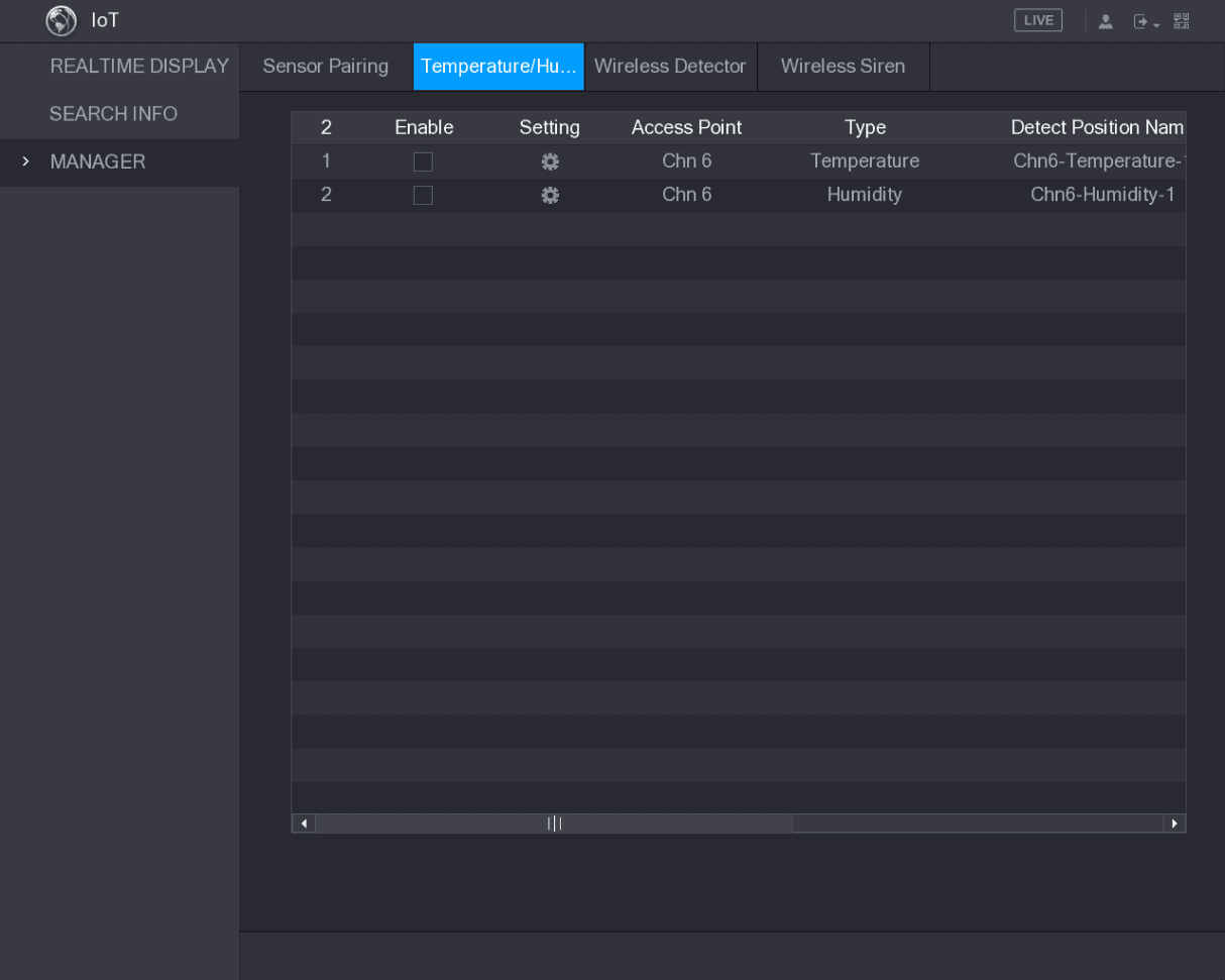
The Temperature/Humidity interface is displayed. See Figure 5-186.
Open the Setting interface
On the humidity information line, click the Setting icon.
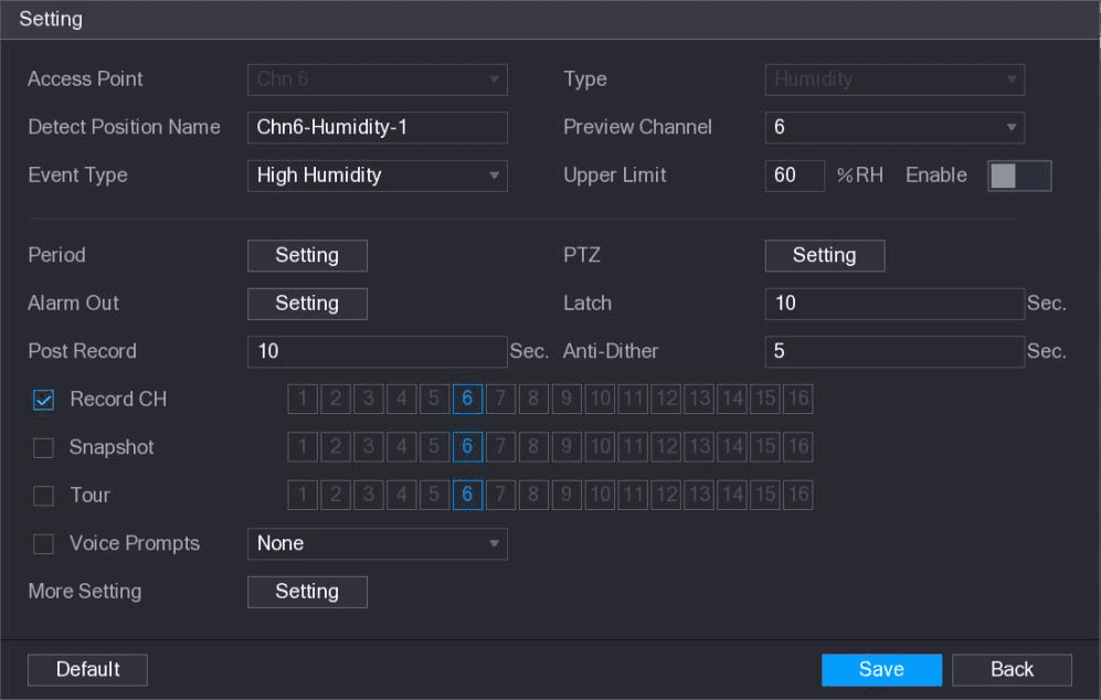
The Setting interface is displayed. See Figure 5-187.
Configure the parameters
Configure the settings for the following parameters. See Table 5-54.
| Parameter | Description |
|---|---|
| Access Point | Indicates the channel that the camera is connected to. |
| Type | Humidity by default. |
| Detect Position Name | Set the detect position name. |
| Preview Channel | Select the channel that you want to preview to help monitor the channel of access point. This channel could be the channel of access point or any other channels according to your actual situation. |
| Event Type / Upper Limit | Select event type as High Humidity or Low Humidity, and set the upper and low humidity limit respectively. For example, select event type as High Humidity and set upper limit as 60, the alarm occurs when the humidity reaches 60%RH. |
| Enable | Enable the alarm function. |
| Period | Define a period during which the alarm setting is active. For more information about setting the period, see "5.10.4.1 Configuring Motion Detect Settings." |
| Alarm Out | Click Setting to display setting interface. General Alarm: Enable alarm activation through the alarm devices connected to the selected output port. External Alarm: Enable alarm activation through the connected alarm box. Wireless Siren: Enable alarm activation through devices connected by USB gateway or camera gateway. |
| PTZ | Click Setting to display the PTZ interface. Enable PTZ linkage actions, such as selecting the preset that you want to be called when an alarm event occurs. |
| Latch | Set a length of time for the Device to delay turning off alarm after the external alarm is cancelled. The value ranges from 0 seconds to 300 seconds, and the default value is 10 seconds. If you enter 0, there will be no delay. |
| Post Record | Set a length of time for the Device to delay turning off recording after the alarm is cancelled. The value ranges from 10 seconds to 300 seconds, and the default value is 10 seconds. |
| Anti-Dither | Configure the time period from end of event detection to the stop of alarm. |
| Snapshot | Select the check box to take a snapshot of the selected channel. To use this function, make sure the snapshot is enabled motion detect alarms in Main Menu > STORAGE > SCHEDULE > Snapshot. |
| Record CH | Select the channel(s) that you want to record. The selected channel(s) starts recording after an alarm occurs. The recording for IoT alarms and auto recording function must be enabled. For details, see "5.1.4.9 Configuring Recorded Video Storage Schedule" and "5.9.1 Enabling Record Control." |
| Tour | Select the check box to enable a tour of the selected channels. To use this function, make sure the tour is enabled and configured in Main Menu > DISPLAY > TOUR. |
| Voice Prompts | Select to enable audio broadcast/voice prompts in response to a temperature alarm event. |
| More Setting | Show Message: Select the Show Message check box to enable a pop-up message in your local host PC. Buzzer: Select the check box to activate a buzzer noise at the Device. Video Matrix: Select the check box to enable the function. When an alarm event occurs, the video output port outputs the settings configured in "Main Menu > DISPLAY > TOUR." (Not all models support this function.) Send Email: Enable the system to send an email notification when an alarm event occurs. To use this function, make sure the email function is enabled in Main Menu > NETWORK > EMAIL. Log: Select the check box to enable the Device to record a local alarm log. |
Save the settings
Click Save to save the settings.
Searching IoT Information
You can search and backup all your IoT data.
To back up the data, you should prepare a USB device and plug it into the Device.
Configure the parameters
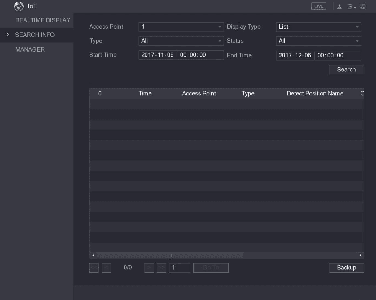
Configure the parameters settings. See Table 5-55.
| Parameter | Description |
|---|---|
| Access Point | Indicates the channel that the camera is connected to. |
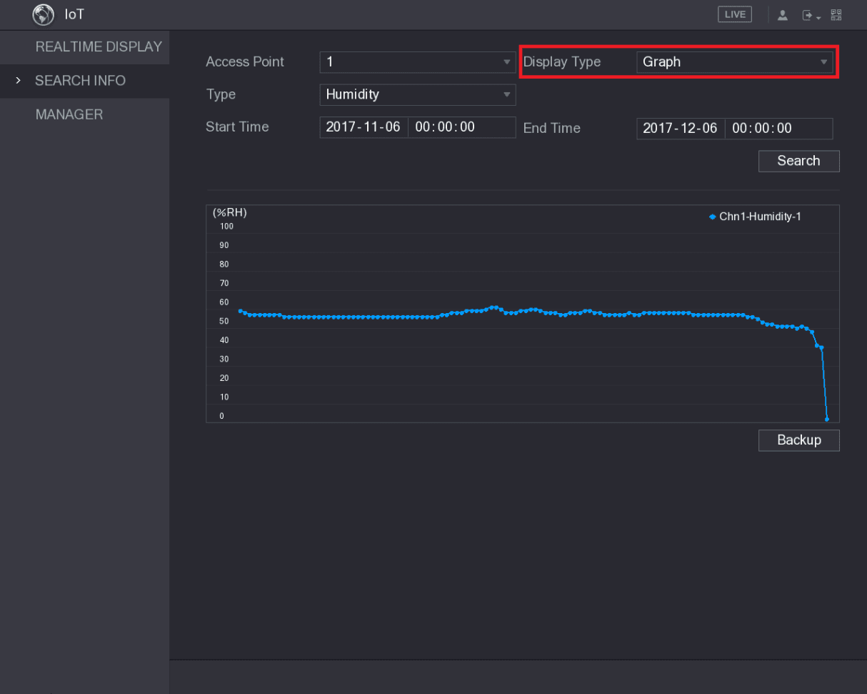
| Display Type | In the Display Type list, select List or Graph. |
| Type | Select the information type that you want to search. You can select Humidity or Temperature. |
| Status | Select the information state that you want to search. This option is available when you select List in the Display Type list. |
| Start Time / End Time | Enter the start time and end time for the information that you want to search. |
Search
Click Search.
The system starts search according to your parameters settings. After searching is finished, the result displays.
For the data displayed in list, see Figure 5-189.
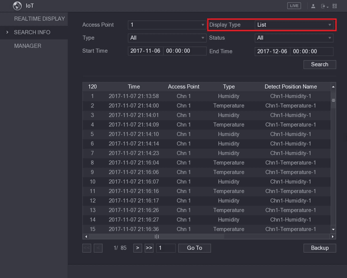
Click Go To to switch result pages.
For the data displayed in graph, see Figure 5-190.
Back up the data
Click Backup. The system starts exporting the data.
After exporting is finished, a Message dialog box is displayed.
Configuring Wireless Siren
You can connect the wireless siren to the Device, when there is an alarm event activated on the Device, the wireless siren generate alarms.
Open Wireless Siren
Select Main Menu > IoT > MANAGER > Wireless Siren.
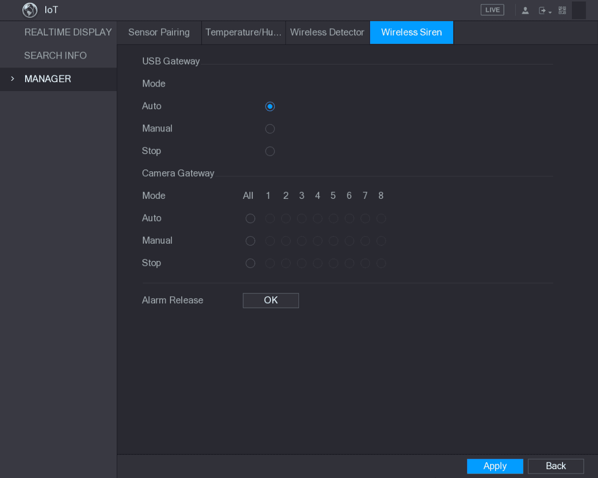
The Wireless Siren interface is displayed. See Figure 5-191.
Configure the wireless alarm output
Configure the settings for the wireless alarm output. For details, see Table 5-56.
| Parameter | Description |
|---|---|
| USB Gateway, Camera Gateway | Auto: Automatically activate alarm if the alarm output function for wireless siren is enabled for specific events. For example, if you want to enable the alarm output through wireless siren for motion detection, see "Alarm Output" parameter in Table 5-39. Manual: Activate alarm immediately. Stop: Do not activate alarm. |
| Alarm Release | Click OK to clear all alarm output status of wireless siren. |
Save the settings
Click Apply to save the settings.
Smart Detection
Configure SMD, human face detection, and IVS smart detection on the CVI DVR to detect persons, vehicles, faces, and behaviors and trigger alarms.
POS and Backup
How to connect the Sapphire Series CVI DVR to a POS machine, search and configure POS overlay settings, and back up recorded videos and snapshots to a USB device.