 Центр помощи LTS Connect
Live View
How to use the Live View screen, control bar, navigation bar, shortcut menu, color and display settings, and tour on the Sapphire Series CVI DVR, and how to enter the Main Menu.
Live View
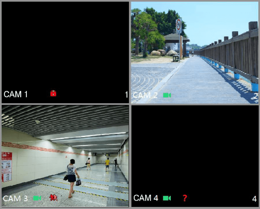
After you logged in the Device, the live view is displayed. See Figure 5-36. The number of channels displayed depends on your model.
To enter the live view screen from other interfaces, click the live view icon on the top right of the screen.
Live View Screen
You can view the live video from the connected cameras through each channel on the screen.
- By default, the system time, channel name and channel number are displayed on each channel window. This setting can be configured by selecting Main Menu > CAMERA > OVERLAY.
- The figure in the bottom right corner represents channel number. If the channel position is changed or the channel name is modified, you can recognize the channel number by this figure and then perform the operations such as record query and playback.
For the icons displayed on each channel, see Table 5-11.
Table 5-11
| Icon | Function |
|---|---|
| Recording | Indicates recording status. This icon displays when the video is being recorded. |
| Motion detection | This icon displays when the motion detection occurs in the scene. |
| Video loss | This icon displays when the video loss is detected. |
| Channel lock | This icon displays when the channel monitoring is locked. |
To switch the position of two channels, point to one of the two channels, and then drag the window to the other channel.
Live View Control Bar
The live view control bar provides you access to perform the operations such as playback, zoom, real-time backup, manual snapshot, voice talk, adding remote devices, and streams switch.
When you move the pointer to the top middle position of a channel window, the live view control bar is displayed. See Figure 5-37 for analog channel and Figure 5-38 for digital channel.
If there is not operation for six seconds after the control bar is displayed, the control bar hides automatically.
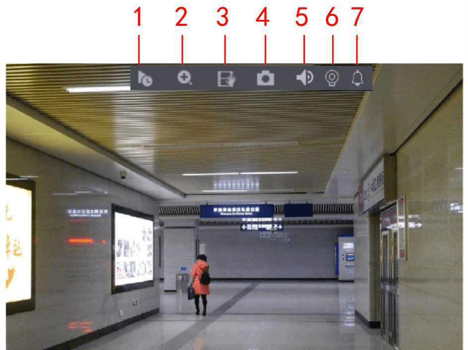
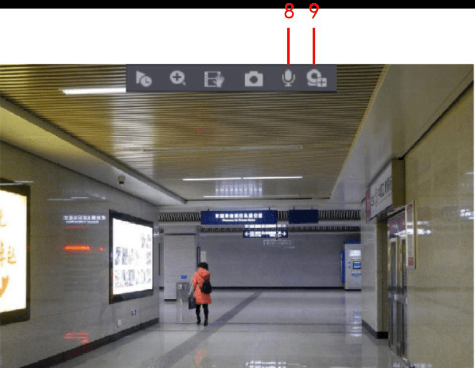
Table 5-12
| No. | Function | No. | Function | No. | Function |
|---|---|---|---|---|---|
| 1 | Instant Play | 4 | Manual Snap | 7 | Siren |
| 2 | Digital Zoom | 5 | Mute | 8 | Audio Talk |
| 3 | Real-time Backup | 6 | White Light | 9 | Camera Registration |
Instant Playback
You can play back the previous five minutes to sixty minutes of the recorded video.
By clicking the Instant Play icon, the instant playback interface is displayed. The instant playback has the following features:
- Move the slider to choose the time you want to start playing.
- Play, pause and close playback.
- The information such as channel name and recording status icon are shielded during instant playback and will not display until exited.
- During playback, screen split layout switch is not allowed.
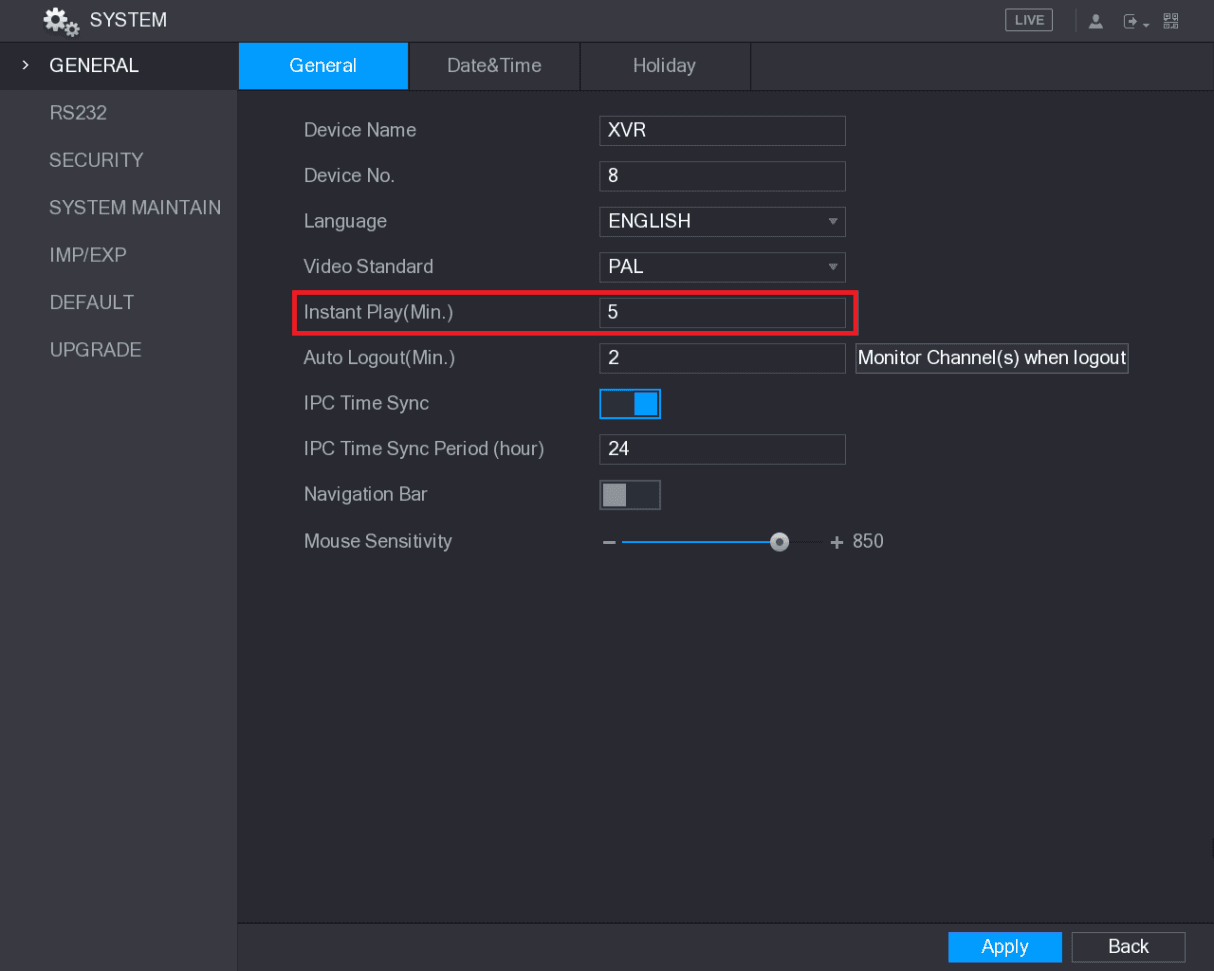
- To change the playback time, select Main Menu > SYSTEM > GENERAL, in the Instant Play box, enter the time you want to play back. See Figure 5-39.
Digital Zoom
You can enlarge a specific area of the image to view the details by either of the following two ways.
-
Click the Digital Zoom icon, the icon switches. Hold down the left mouse button to select the area you want to enlarge. The area is enlarged after the left mouse button is released.
-
Point to the center that you want to enlarge, rotate the wheel button to enlarge the area.
-
For some models, when the image is enlarged in the first way described previously, the selected area is zoomed proportionally according to the window.
-
When the image is in the enlarged status, you can drag the image toward any direction to view the other enlarged areas.
-
Right-click on the enlarged image to return the original status.
Real-time Backup
You can record the video of any channel and save the clip into a USB storage device.
By clicking the Real-time Backup icon, the recording is started. To stop recording, click this icon again. The clip is automatically saved into the connected USB storage device.
Manual Snapshot
You can take one to five snapshots of the video and save into a USB storage device.
By clicking the Manual Snap icon, you can take snapshots. The snapshots are automatically saved into the connected USB storage device. You can view the snapshots on your PC.
To change the quantity of snapshots, select Main Menu > CAMERA > ENCODE > Snapshot, in the Manual Snap list, select the snapshot quantity.
Mute (Analog channel only)
You can mute the video sound by clicking the Mute icon. This function is supported in single-channel view.
White Light (Supported on camera with white light function)
Click the White Light icon to manually control the camera to turn on the white light function.
Siren (Supported on camera with siren function)
Click the Siren icon to manually control the camera to generate alarm sound.
Bidirectional Talk (Digital channel only)
You can perform the voice interaction between the Device and the remote device to improve efficiency of emergency. This function is supported only when the remotely connected IPC device supports bidirectional talk.
- Click the Audio Talk icon, the icon switches, the bidirectional talk of the remote device is turned on. The bidirectional talk of other digital channels is disabled.
- Click the icon again to cancel the bidirectional talk. The bidirectional talk of other digital channels is resumed.
Remote Devices (Digital channel only)
You can view the information of remote devices and add new remote devices to replace the current connected devices.
By clicking the Camera Registration icon, the Camera Registration interface is displayed. For details about adding the remote devices, see 5.6 Configuring Remote Devices.
Navigation Bar
You can access the functions to perform operations through the function icons on the navigation bar. For example, you can access Main Menu and switch window split mode. See Figure 5-40.
The navigation bar is disabled by default. It does not appear in the live view screen until it is enabled. To enable it, select Main Menu > SYSTEM > GENERAL, enable the Navigation Bar, and then click Apply.

Table 5-13
| Icon | Function |
|---|---|
| Main Menu | Open Main Menu. |
| Expand/Condense | Expand or condense the navigation bar. |
| View layout | Select view layout. |
| Previous screen | Go to the previous screen. |
| Next screen | Go to the next screen. |
| Tour | Enable tour function. The icon switches. |
| PTZ | Open the PTZ control panel. For details, see 5.4 Controlling PTZ Cameras. |
| Color | Open the Color Setting interface. For details, see 5.2.5 Color Setting. This function is supported only in single-channel layout. |
| Search | Open the record search interface. For detail, see 5.9 Playing Back Video. |
| Event | Open the EVENT interface to view the device alarm status. For details, see 5.20.3 Viewing Event Information. |
| Channel Info | Open the CHANNEL INFO interface to display the information of each channel. |
| Camera Registration | Open the CAMERA REGISTRATION interface. For details, see 5.6.1 Adding Remote Devices. |
| Network | Open the NETWORK interface. For details, see 5.15.1 Configuring Network Settings. |
| HDD Manager | Open the HDD MANAGER interface. For details, see 5.18.3 Configuring HDD Manager. |
| USB Manager | Open the USB MANAGER interface. For details about USB operations, see 5.14.2 Backing up Files, 5.20.2 Viewing Log Information, 5.19.5 Exporting and Importing System Settings, 5.19.7 Upgrading the Device. |
Shortcut Menu
You can quickly access some function interfaces such as main menu, record search, PTZ setting, color setting and select the view split mode.
Right-click on the live view screen, the shortcut menu is displayed. See Figure 5-41. For details about the functions of shortcut menu, see Table 5-14.
After you access any interface through shortcut menu, you can return to the previous screen by right-clicking on the current screen.
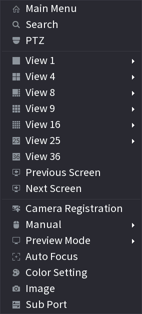
Table 5-14
| Function | Description |
|---|---|
| Main Menu | Open Main Menu interface. |
| Search | Open the PLAYBACK interface where you can search and play back record files. |
| PTZ | Open the PTZ interface. |
| View Layout | Configure the live view screen as a single-channel layout or multi-channel layout. |
| Previous Screen / Next Screen | Click Previous Screen to go to the previous screen. For example, if you are using 4-split mode, the first screen is displaying the channel 1-4, click Next screen, you can view channel 5-8. |
| Camera Registration | Open the CAMERA REGISTRATION interface. For details, see 5.6 Configuring Remote Devices, Adding Remote Devices. |
| Manual | Select Record, you can configure the recording mode as Auto or Manual, or stop the recording. You can also enable or disable snapshot function. Select Alarm Out, you can configure alarm output settings. |
| Preview Mode | Select General, the layout of live view screen is as default. Select Show Face List, the detected face snapshots are displayed in the bottom of the live view screen. |
| Auto Focus | Point to the channel window and right-click on it to open the shortcut menu, and then click Auto Focus. Not all cameras support this function. |
| Color Setting | Open the COLOR interface where you can adjust the video image color. |
| Image | Click to modify the camera properties. |
| Sub Port | Click to switch to extra screen control. |
Color Setting
You can adjust the video image color effect such as sharpness, brightness, and contrast. The parameters are different according to the connected camera type. Take analog channel as an example.
In the live view screen, right-click on the analog channel to see the shortcut menu, and then select Color Setting, the COLOR interface is displayed. See Figure 5-42.
For details, see 5.5.1 Configuring Image Settings.
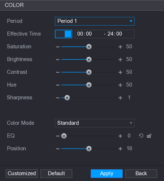
Table 5-15
| Parameter | Description |
|---|---|
| Period | Divide 24 hours into two periods and configure the corresponding color settings. |
| Effective Time | Enable the function and then set the effective time for each period. |
| Sharpness | Adjust the sharpness of image edge. The bigger the value is, the more obvious the image edge, and the noise is also greater. The value ranges from 1 to 15. The default value is 1. |
| Hue | Adjust the hue of image. The value ranges from 0 to 100. The default value is 50. |
| Brightness | Adjust the image brightness. The value ranges from 0 to 100. The default value is 50. The bigger the value is, the brighter the image will become. You can adjust this value when the image as a whole looks dark or bright. However, the image is likely to become dim if the value is too big. The recommended range is between 40 and 60. |
| Contrast | Adjust the image contrast. The bigger the value is, the more obvious the contrast between the light area and dark area will become. You can adjust this value when the contrast is not obvious. However, if the value is too big, the dark area is likely to become darker and the light area over exposed. If the value is too small, the image is likely to become dim. The value ranges from 0 to 100. The default value is 50. The recommended range is between 40 and 60. |
| Saturation | Adjust the color shades. The bigger the value, the lighter the color will become. This value does not influence the general image lightness. The value ranges from 0 to 100. The default value is 50. The recommended range is between 40 and 60. |
| Color Mode | In the Color Mode list, you can select Standard, Soft, Bright, Colorful, Bank, Customized 1, Customized 2, Customized 3, and Customized 4. The sharpness, hue, brightness, contrast and saturation will adjust automatically according to the selected color mode. |
| EQ | Enhance the image effect. Adjust the effect value. Click to adjust the image to the optimized effect automatically. Click to lock the current effect setting. Only HD analog channel supports this function. |
| Position | Adjust the display position of the image in the channel window. The value indicates pixel. The default value is 16. This function is only supported by analog channel. |
| Customized | You can customize four color modes. 1. Click Customized. The Customized Color interface is displayed. 2. In the Color Mode list, select Customized 1, for example. Then configure the settings for sharpness, hue, brightness, contrast and saturation. If you select All, the configuration will applies to all four customized color modes. 3. Click OK. 4. On the COLOR interface, in the Color Mode list, you can select the customized color mode. |
Live View Display
Configuring Display Settings
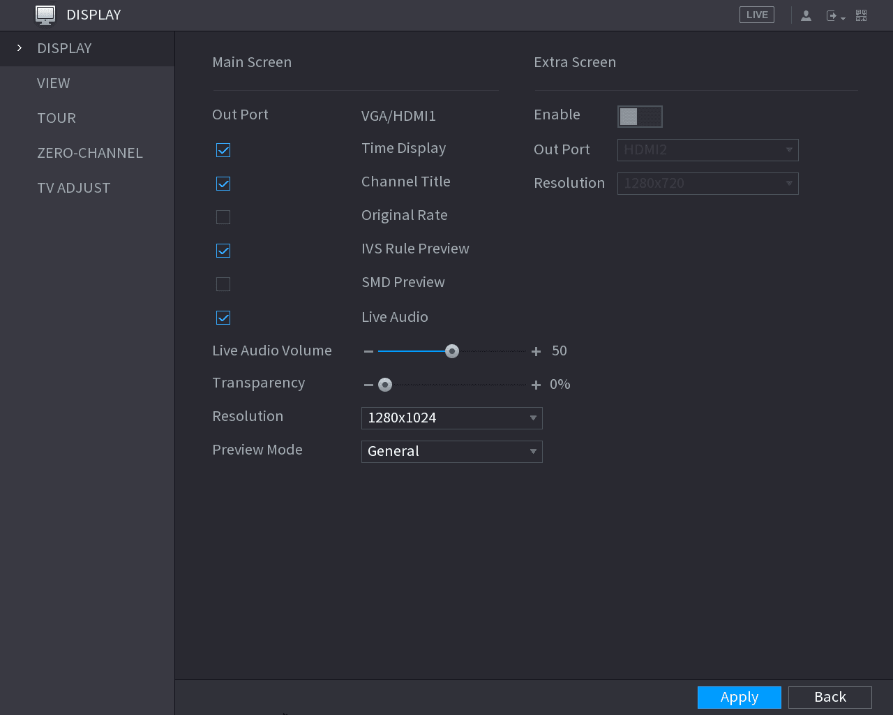
You can configure the display effect such as displaying time title and channel title, adjusting image transparency, and selecting the resolution.
Open the DISPLAY interface
Select Main Menu > DISPLAY > Display.
The DISPLAY interface is displayed. See Figure 5-43.
Configure the display parameters
Configure the settings for the display parameters. See Table 5-16.
Table 5-16
| Parameter | Description |
|---|---|
| Main Screen — Out Port | Indicates the main screen port. |
| Main Screen — Time Display | Select the Time Display check box, the current system time displays in each channel window in live view screen. To hide the time, clear the check box. |
| Main Screen — Channel Title | Select the Channel Title check box, the channel name, channel number and recording status display in each channel window in live view screen. To hide the time, clear the check box. |
| Main Screen — Original Rate | Select the Original Rate check box, the video image displays in its actual size in the channel window. |
| Main Screen — IVS Rule Preview | Select the IVS Rule Preview check box to enable IVS rule preview function. |
| Main Screen — SMD Preview | Select the SMD Preview check box to enable SMD preview function. Maximum three SMD boxes can be displayed at the same time. |
| Main Screen — Live Audio | Select the Live Audio check box to enable the audio adjustment function in the channel window on the live view screen. |
| Main Screen — Live Audio Volume | Move the slider to adjust the volume of live audio. |
| Main Screen — Transparency | Configure the transparency of the graphical user interface (GUI). The higher the value, the more transparent the GUI becomes. |
| Main Screen — Resolution | Select resolution for the video. The default resolution for VGA port and HDMI port is 1280×1024. Some of the resolution options might not be supported on the HDMI port. |
| Main Screen — Preview Mode | General: No information is displayed on the channel window. Show Face List: Displays the detected face snapshots taken as a result of face detection on the bottom of the live view screen. Not all models support this function. |
| Extra Screen — Enable | Enable extra screen function. After this function is enabled, you can select which port as extra screen port, and the other port automatically becomes the main screen port. |
| Extra Screen — Out Port | Select the VGA port or HDMI port as the port connected by a secondary monitor. For example, if you select HDMI port as the extra screen port, the VGA port automatically becomes the main screen port. A device that supports HDMI2 can only select HDMI2. |
| Extra Screen — Resolution | Select resolution for the video. The default resolution for VGA port and HDMI port is 1280×720. Some of the resolution options might not be supported on the HDMI port. |
- The main menu does not display on the extra screen.
- If you do not enable the extra screen function, both the VGA port and HDMI port display the same image.
Configuring Viewing Layout
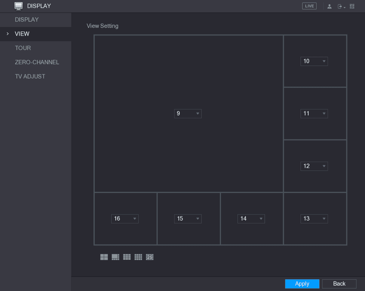
You can configure the view layout in the live view screen.
Open the View Setting interface
Select Main Menu > DISPLAY > VIEW.
The View Setting interface is displayed. See Figure 5-44.

Configure the view layout
Configure the view layout by clicking the layout buttons on the bottom. See Figure 5-45.

For example, click the layout button and select 9-16, the view layout changes immediately, see Figure 5-46.
Adjust the position of channels
Adjust the position of channels if needed. In the channel list, for example, in the channel 9 list, you can select 10, and then the channel 9 and channel 10 exchange positions.
Save the settings
Click Apply to complete the settings.
The live view screen displays the same layout as configured in this section.
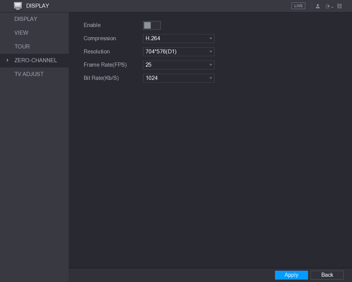
Configuring Zero-Channel Settings
You can view several video sources on one channel on the web end.
Open the ZERO-CHANNEL interface
Select Main Menu > DISPLAY > ZERO-CHANNEL.
The ZERO-CHANNEL interface is displayed. See Figure 5-47.
Configure the zero-channel parameters
Configure the settings for the zero-channel parameters. See Table 5-17.
Save the settings
Click Apply to save the settings.
In the live interface on the web, click the layout icon to select one of the multi-channel modes, and then you can view the local video image.
Table 5-17
| Parameter | Description |
|---|---|
| Enable | Enable zero-channel function. |
| Compression | In the Compression list, select the video compression standard according to the device capability. The default is H.265. |
| Resolution | In the Resolution list, select the video resolution. The default is 704×576 (D1). |
| Frame Rate (FPS) | Select a value between 1 and 25 for PAL standard, and between 1 and 30 for NTSC standard. The actual arrange is decided and selected dependent on the Device capability. |
| Bit Rate (Kb/S) | The default value is 1024Kb/S. The actual arrange is decided and selected dependent on the Device capability and frame rate. |
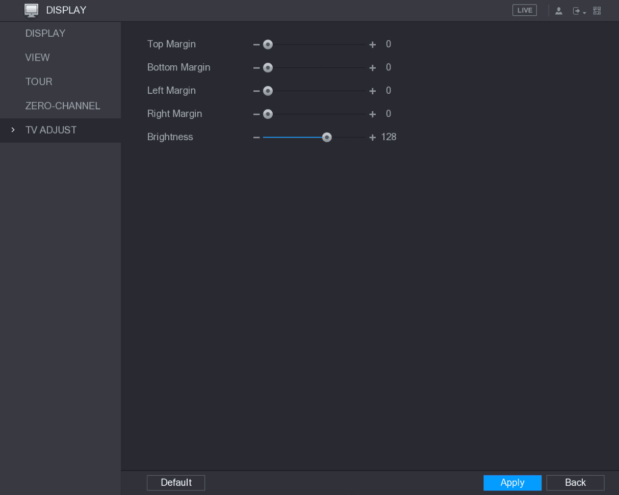
Configuring TV
Not all models support this function.
You can adjust the border margins in top, bottom, left and right directions as well as the brightness of the monitor connected to the Video out port of the Device.
Open the TV ADJUST interface
Select Main Menu > DISPLAY > TV ADJUST.
The TV ADJUST interface is displayed. See Figure 5-48.
Configure and save
Configure the parameters according to your actual situation.
Click Apply to complete the settings.
Configuring Tour Settings
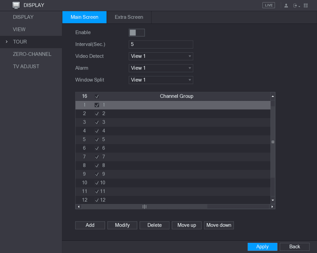
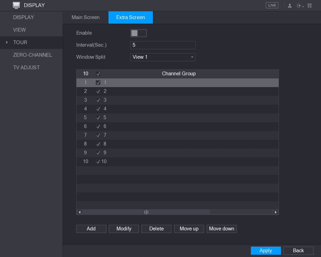
You can configure a tour of selected channels to repeat playing videos. The videos display in turn according to the channel group configured in tour settings. The system displays one channel group for a certain period and then automatically changes to the next channel group.
Open the TOUR interface
Select Main Menu > DISPLAY > TOUR.
The TOUR interface is displayed. There are Main Screen tab and Extra Screen tab, see Figure 5-49 and Figure 5-50.
Configure the tour parameters
Configure the settings for the tour parameters for both Main Screen and Extra Screen. See Table 5-18.
Save the settings
Click Apply to save the settings.
Table 5-18
| Parameter | Description |
|---|---|
| Enable | Enable tour function. |
| Interval (Sec.) | Enter the amount of time that you want each channel group displays on the screen. The value ranges from 5 seconds to 120 seconds, and the default value is 5 seconds. |
| Video Detect, Alarm | Select the View 1 or View 8 for Motion Detect tour and Alarm Tour (system alarm events). |
| Window Split | In the Window Split list, select View 1, View 4, View 8, or other modes that are supported by the Device. |
| Channel Group | Display all channel groups under the current Window Split setting. Add a channel group: Click Add, in the pop-up Add Group channel, select the channels to form a group, and then click Save. Delete a channel group: Select the check box of any channel group, and then click Delete. Edit a channel group: Select the check box of any channel group and then click Modify, or double-click on the group. The Modify Channel Group dialog box is displayed. You can regroup the channels. Click Move up or Move down to adjust the position of channel group. |
- On the top right of the live view screen, use the left mouse button or press Shift to switch between the tour-on state (image switching is allowed) and the tour-off state (image switching is not allowed) to turn on/off the tour function.
- On the navigation bar, click the tour icon to enable the tour and click it again to disable it.
Adding a Channel Group
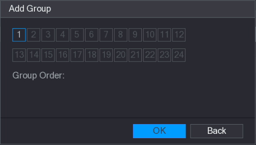
Select the channels
Select the channels that you want to group for tour. See Figure 5-52.
If you want to select more than one channel, in the Window Split list, do not select View 1.
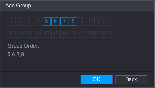
Complete the settings
Click OK to complete the settings.
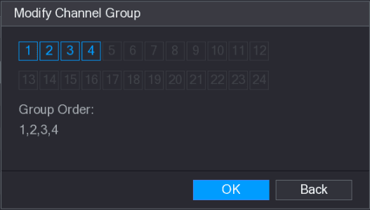
Modifying a Channel Group
Double-click on a channel group, the Modify Channel Group interface is displayed. See Figure 5-53.
You can modify channel group and click OK to complete the settings.
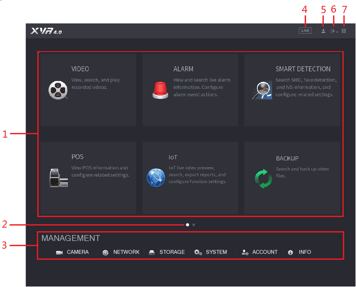
Entering Main Menu
Right-click on the live view screen, the shortcut menu is displayed, Click Main Menu and then login the system. The Main Menu is displayed, see Figure 5-54.
Initial Settings
Boot up, initialize, set passwords, reset a forgotten password, and complete the Startup Wizard for the Sapphire Series CVI DVR.
Controlling PTZ Cameras
Configure the PTZ connection, operate the basic and expanded PTZ control panels, set up and call presets, tours, patterns, AutoScan, AutoPan, and AUX functions, and call the OSD menu of a coaxial camera on the Sapphire Series CVI DVR.