 LTS Connect 說明中心
Quick Settings
Use the NVR startup wizard to configure general settings, date and time, holidays, basic network and P2P, remote device registration, RAID, and the record and snapshot schedules.
After you start the Device and finish the startup wizard welcome screen, you can use Quick Settings to configure the basic parameters of the NVR step by step. See Figure 4-15.
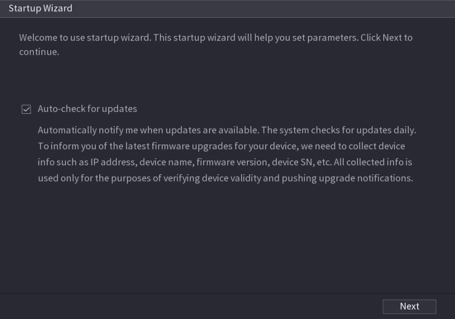
- If you select the Auto-check for updates check box, the system will notify you automatically when updates are available.
- After the auto-check function is enabled, to notify you to update timely, the system will collect the information such as IP address, device name, firmware version, and device serial number. The collected information is only used to verify the legality of the Device and push upgrade notices.
- If you cancel the Auto-check for updates check box, the system will not perform automatic checks.
General
You can set NVR basic information such as system date, holiday and etc. You can also configure general settings by selecting Main Menu > SYSTEM > General.
General
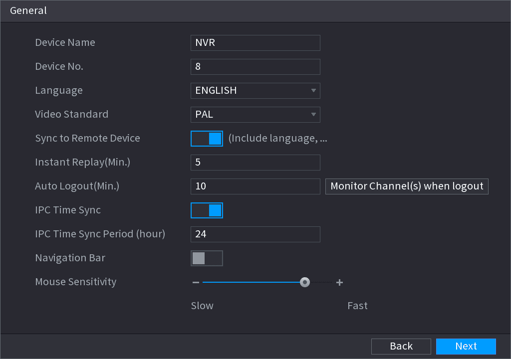
You can set device basic information such as device name, serial number.
Set parameters
Set parameters. See Table 4-3.
| Parameter | Description |
|---|---|
| Device Name | In the Device Name box, enter the Device name. |
| Device No. | In the Device No. box, enter a number for the Device. |
| Language | In the Language list, select a language for the Device system. |
| Video Standard | In the Video Standard list, select PAL or NTSC according to your actual situation. |
| Sync to Remote Device | Enable this function; the NVR can synchronize information with the remote device such as Language, video standard, time zone. |
| Instant Play (Min.) | In the Instant Play box, enter the time length for playing back the recorded video. The value ranges from 5 to 60. On the live view control bar, click the instant playback button to play back the recorded video within the configured time. |
| Auto Logout (Min.) | In the Auto Logout box, enter the standby time for the Device. The Device automatically logs out when it is not working for the configured time period. You need to login the Device again. The value ranges from 0 to 60. 0 indicates there is not standby time for the Device. Click Monitor Channel(s) when logout. You can select the channels that you want to continue monitoring when you logged out. |
| IPC Time Sync | Syncs the Device time with IP camera. |
| IPC Time Sync Period (hour) | In the IPC Time Sync Period box, enter the interval for time sync. |
| Auto logout | You can set auto logout interval once login user remains inactive for a specified time. Value ranges from 0 to 60 minutes. |
| Navigation Bar | Enable the navigation bar. When you click on the live view screen, the navigation bar is displayed. |
| Mouse Sensitivity | Adjust the speed of double-click by moving the slider. The bigger the value is, the faster the speed is. |
Save settings
Click Next button to save settings.
Date and Time
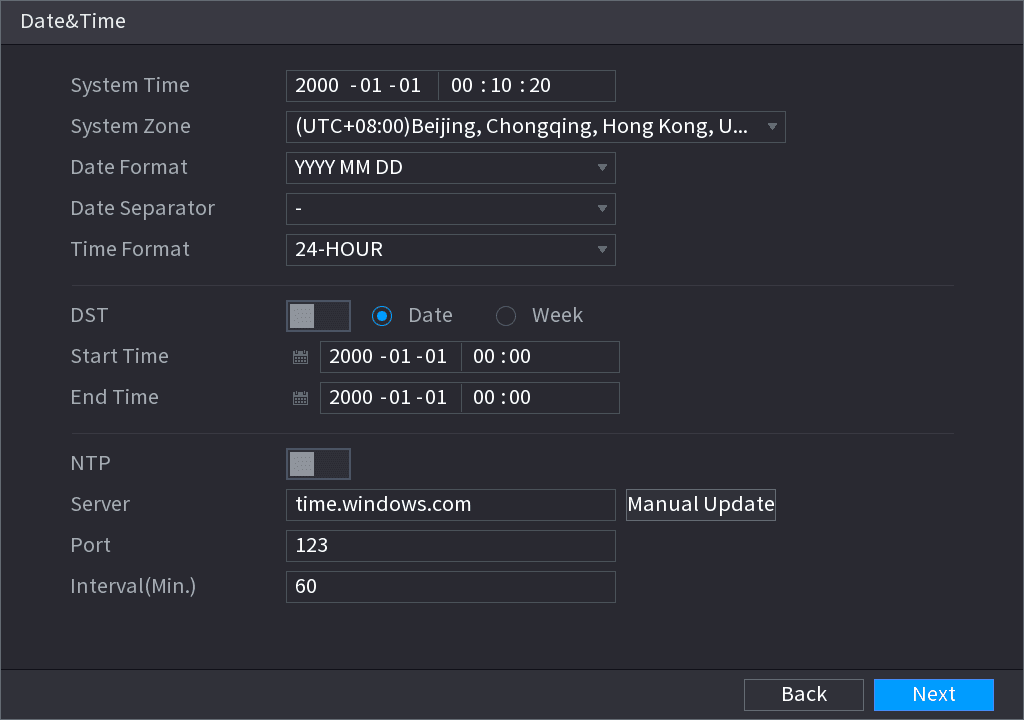
You can set device time. You can enable NTP (Network Time Protocol) function so that the device can sync time with the NTP server.
You can also configure date and time settings by selecting Main Menu > SYSTEM > GENERAL > Date&Time.
Configure date and time parameters
Configure the settings for date and time parameters. See Table 4-4.
| Parameter | Description |
|---|---|
| System Time | In the System Time box, enter time for the system. Click the time zone list, you can select a time zone for the system, and the time in adjust automatically. Do not change the system time randomly; otherwise the recorded video cannot be searched. It is recommended to avoid the recording period or stop recording first before you change the system time. |
| System Zone | In the System Zone list, select a time zone for the system. |
| Date Format | In the Date Format list, select a date format for the system. |
| Date Separator | In the Date Separator list, select a separator style for the date. |
| Time Format | In the Time Format list, select 12-HOUR or 24-HOUR for the time display style. |
| DST | Enable the Daylight Saving Time function. Click Week or click Date. |
| Start Time / End Time | Configure the start time and end time for the DST. |
| NTP | Enable the NTP function to sync the Device time with the NTP server. |
| Server | In the Server box, enter the IP address or domain name of the corresponding NTP server. Click Manual Update, the Device starts syncing with the server immediately. |
| Port | The system supports TCP protocol only and the default setting is 123. |
| Interval (Min.) | In the Interval box, enter the amount of time that you want the Device to sync time with the NTP server. The value ranges from 0 to 65535. |
Save settings
Click Next button to save settings.
Holiday
Here you can add, edit, delete holiday. After you successfully set holiday information, you can view holiday item on the record and snapshot period.
You can also configure holiday settings by selecting Main Menu > SYSTEM > GENERAL > Holiday.
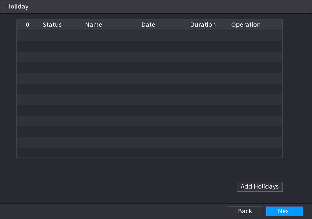
Open the Add Holidays interface
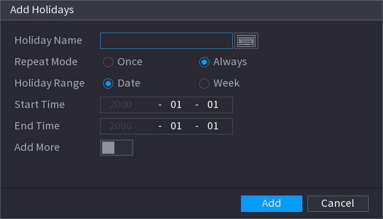
Click Add Holidays button, the Add Holidays interface is displayed. See Figure 4-19.
Set holiday details
Set holiday name, repeat mode and holiday mode.
Click Add more to add new holiday information.
Add the holiday
Click Add button, you can add current holiday to the list.
- Click the dropdown list of the state; you can enable/disable holiday date.
- Click the edit icon to change the holiday information. Click the delete icon to delete current date.
Save settings
Click Next button to save settings.
Basic Network Settings
You can set device IP address, DNS (Domain Name System) information. You can also configure basic network settings by selecting Main Menu > NETWORK > TCP/IP.
Preparation
Make sure the device has properly connected to the network.
Open the TCP/IP interface
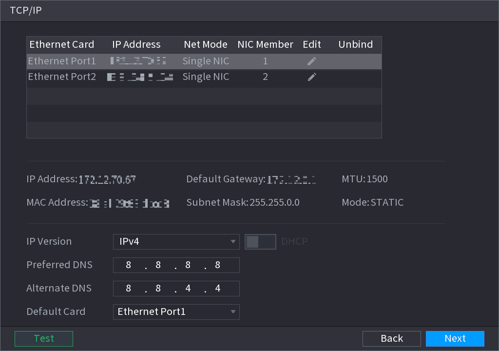
Click Next. The TCP/IP interface is displayed. See Figure 4-20.
Different series products have different Ethernet adapter amount and type. Refer to the actual product.
Set parameters
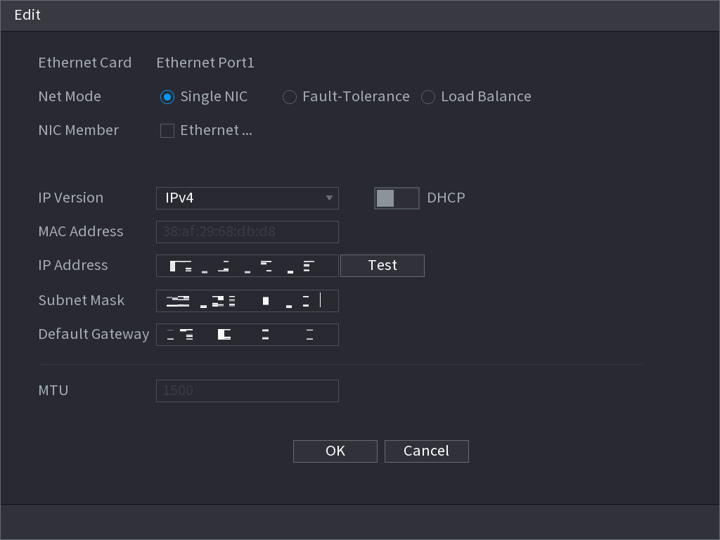
Set parameters. See Table 4-5.
| Parameter | Description |
|---|---|
| Net Mode | Multi-address: Two Ethernet ports work separately through either of which you can request the Device to provide the services such as HTTP and RTSP. You need to configure a default Ethernet port (usually the Ethernet port 1 by default) to request the services from the device end such as DHCP, Email and FTP. If one of the two Ethernet ports is disconnected as detected by networking testing, the system network status is regarded as offline. Fault Tolerance: Two Ethernet ports share one IP address. Normally only one Ethernet port is working and when this port fails, the other port will start working automatically to ensure the network connection. When testing the network status, the network is regarded as offline only when both of the two Ethernet ports are disconnected. The two Ethernet ports are used under the same LAN. Load Balance: Two network cards share one IP address and they are working at the same time to share the network load averagely. If one of them fails, the other can continue working normally. When testing the network status, the network is regarded as offline only when both of the two Ethernet ports are disconnected. The two Ethernet ports are used under the same LAN. The Device with single Ethernet port does not support this function. |
| Default Ethernet Port | In the Ethernet Card list, select an Ethernet port as a default port. This setting is available only when the Multi-address is selected in the Net Mode list. |
| IP Version | In the IP Version list, you can select IPv4 or IPv6. Both versions are supported for access. |
| MAC Address | Displays the MAC address of the Device. |
| DHCP | Enable the DHCP function. The IP address, subnet mask and default gateway are not available for configuration once DHCP is enabled. If DHCP is effective, the obtained information will display in the IP Address box, Subnet Mask box and Default Gateway box. If not, all values show 0.0.0.0. If you want manually configure the IP information, disable the DHCP function first. If PPPoE connection is successful, the IP address, subnet mask, default gateway, and DHCP are not available for configuration. |
| IP Address / Subnet Mask | Enter the IP address and configure the corresponding subnet mask and default gateway. |
| Default Gateway | IP address and default gateway must be in the same network segment. |
| DNS DHCP | Enable the DHCP function to get the DNS address from router. |
| Preferred DNS | In the Preferred DNS box, enter the IP address of DNS. |
| Alternate DNS | In the Alternate DNS box, enter the IP address of alternate DNS. |
| MTU | In the MTU box, enter a value for network card. The value ranges from 1280 byte through 1500 byte. The default is 1500. |
| Test | Click Test to test if the entered IP address and gateway are interworking. |
Confirm NIC settings
Click OK to NIC settings. Device goes back to TCP/IP interface.
Set network parameters
Set network parameters. See Table 4-6.
| Parameter | Description |
|---|---|
| IP Version | There are two options: IPv4 and IPv6. Right now, system supports these two IP address format and you can access via them. |
| Preferred DNS server | DNS server IP address. |
| Alternate DNS server | DNS server alternate address. |
| MAC Address | Displays the MAC address of the Device. |
| DHCP | Enable the DHCP function. The IP address, subnet mask and default gateway are not available for configuration once DHCP is enabled. If DHCP is effective, the obtained information will display in the IP Address box, Subnet Mask box and Default Gateway box. If not, all values show 0.0.0.0. If you want manually configure the IP information, disable the DHCP function first. If PPPoE connection is successful, the IP address, subnet mask, default gateway, and DHCP are not available for configuration. |
| LAN download | System can process the downloaded data first if you enable this function. The download speed is 1.5X or 2.0X of the normal speed. For IPv6 version, the IP address, default gateway, preferred DNS; alternate DNS is 128-digit. Fill in all items here. This function is for some series product only. |
Complete the settings
Click Next to complete the settings.
P2P
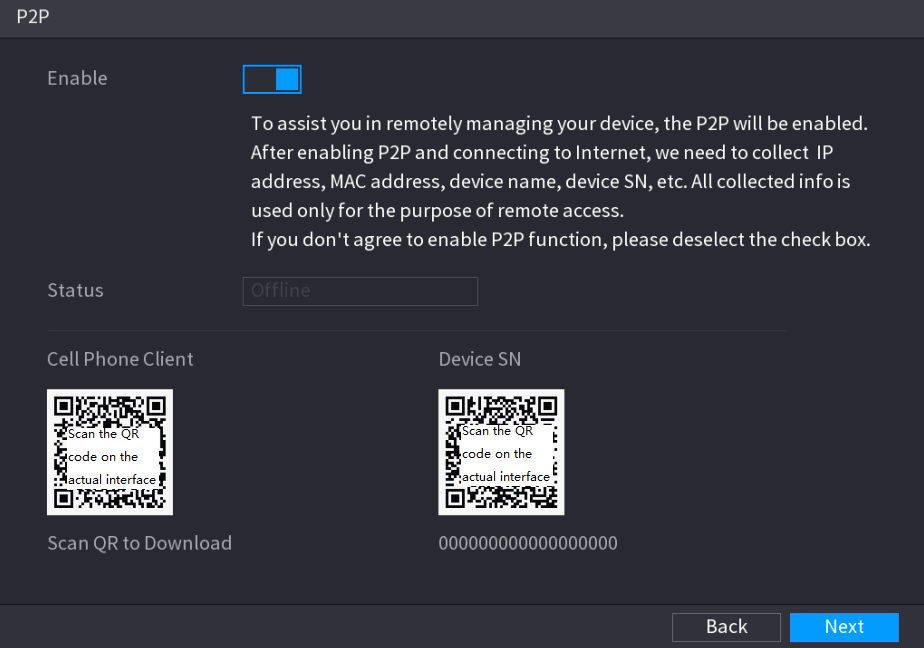
Scan the QR code, download the App to the cell phone, you can use the smart phone to add the device.
- Scan the QR code on the actual interface to download the cell phone app. Register an account and then use.
- Go to the www.easy4ip.com to register an account and use the SN to add a device. Refer to the P2P operation manual for detailed information.
Before use the P2P function, make sure the NVR has connected to the WAN.
Open the P2P interface
Click Next button. The P2P interface is displayed. See Figure 4-22.
Select Main Menu > Network > P2P, you can go to P2P interface too.
Enable P2P
Check the box to enable P2P function.
After the P2P function is enabled and connected to the Internet, the system will collects your information for remote access, and the information includes but not limited to email address, MAC address, and device serial number.
Complete setup
Click Next button to complete setup. The status is online if the P2P registration is successful.
Client Operation
Download the application
Use your cell phone to scan the QR code under Cell Phone Client to download the application.
Open the application
On your cell phone, open the application, and then tap the menu button.
Start adding the device
The menu is displayed. You can start adding the device.
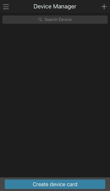
- Tap Device Manager. The Device Manager interface is displayed. See Figure 4-23.
-
Tap the add icon on the top right corner. The interface requiring device initialization is displayed. A pop-up message reminding you to make sure the Device is initialized is displayed.
-
Tap OK.
- If the Device has not been initialized, Tap Device Initialization to perform initializing by following the onscreen instructions.
- If the Device has been initialized, you can start adding it directly.
-
Tap Add Device. The Add Device interface is displayed. See Figure 4-24.
You can add wireless device or wired device. The Manual takes adding wired device as an example.
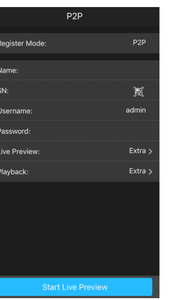
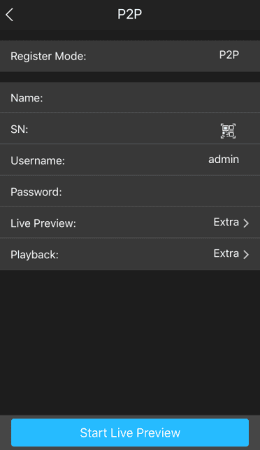
- Tap P2P. The P2P interface is displayed. See Figure 4-25.
-
Enter a name for the NVR, the username and password, scan the QR code under Device SN.
-
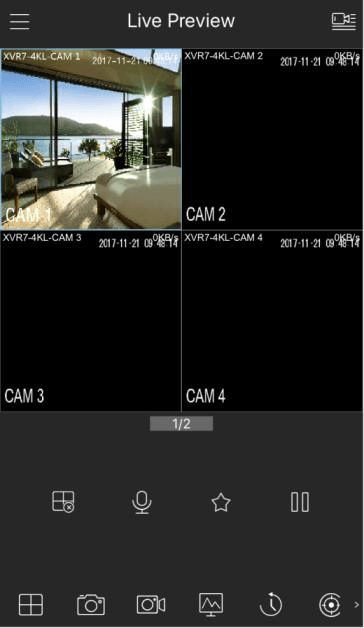
Tap Start Live Preview. The Device is added and displayed on the live view interface of the cell phone. See Figure 4-26.
Registration
If you do not select Smart add function during the initialization process, go to the remote Device interface to register a remote device.
After adding remote device, the device can receive, store, and manage the video streams of the remote device. You can view, browse, play back and manage several remote devices at the same time.
Open the Registration interface
On the P2P interface, click Next button. The REGISTRATION interface is displayed. See Figure 4-27.
There are two ways to go to Registration interface.
- Select Main Menu > CAMERA > REGISTRATION > Camera Registration, you can go to the Camera Registration interface.
- On the preview interface, right click mouse and then select Camera Registration.
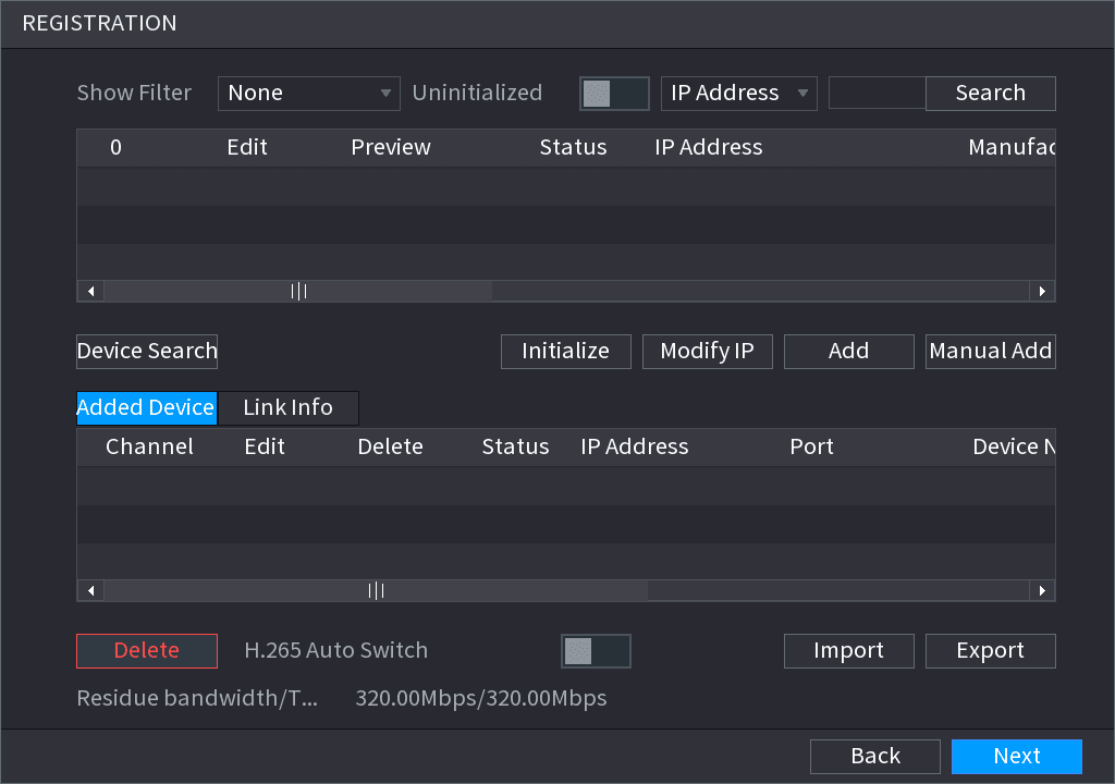
Register remote device
Register remote device.
Search and then add
- Click Device Search. System displays searched devices at the upper pane.
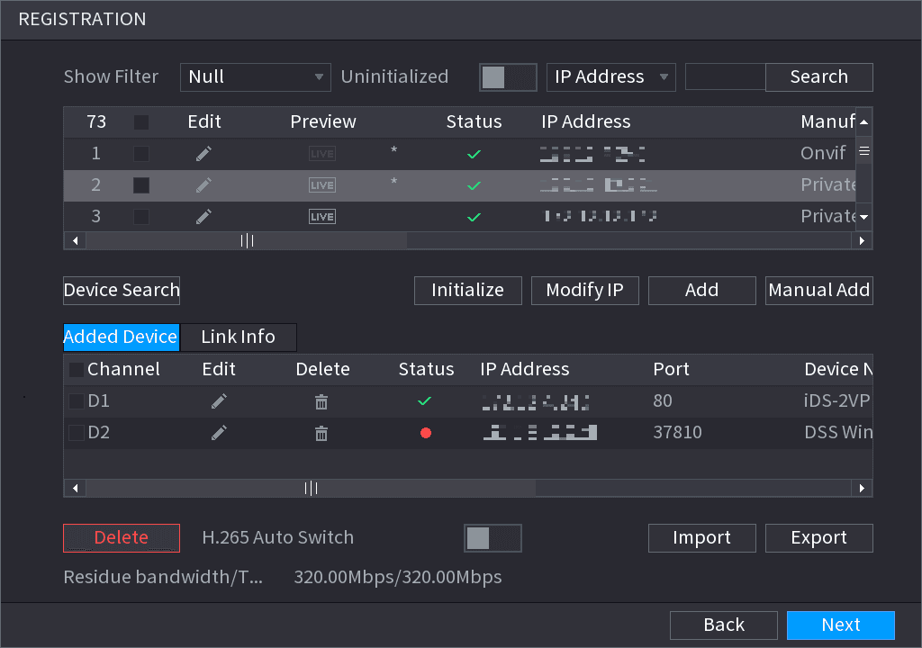
- Double-click a remote device, or select a remote device and then click Add to register it to the Added Device list. See Figure 4-28. Refer to Table 4-7 to set parameters.
The search results do not display the remote camera that has registered to the system.
| Parameter | Description |
|---|---|
| Uninitialized | Enable the Uninitialized function, the uninitialized devices out of the searched devices are displayed in the searched device list. |
| Initialize | Select the uninitialized device from the uninitialized device list, and the click Initialize to start initializing device. |
| Show Filter | In the Show Filter list, select the remote device type that you want to display in the searched device list. None: Display all types of devices. IPC: Display the front-end devices. DVR: Display all storage devices such as NVR, DVR and HCVR. OTHER: Display the devices that do not belong to IPC or DVR type. |
| Searched Device List | Displays the searched devices. You can view the device information such as status, IP address. |
| Device Search | Click Device Search, the searched devices display in the searched device list. To adjust the display sequence, in the title line, you can click the IP address, Manufacturer, Type, MAC Address, Port, or Device Name text. For example, click the IP address text, the sequence icon is displayed. "*" is displayed next to the added device. |
| Add | In the Searched Device List area, select the device that you want to add. |
| Manual Add | Add the device by manually configuring settings such as IP address, channel selection. |
| Added Device List | Displays the added devices. You can edit and delete the device, and view the device information. |
| Delete | Select the check box of the added device, and then click Delete to delete the added device. |
| Import | Select the searched devices and then click Import to import the devices in batches. |
| Export | Select the added devices and then click Export. The exported devices information is saved into the USB storage device. |
Manual Add
- Click Manual Add. The Manual Add interface is displayed. See Figure 4-29.
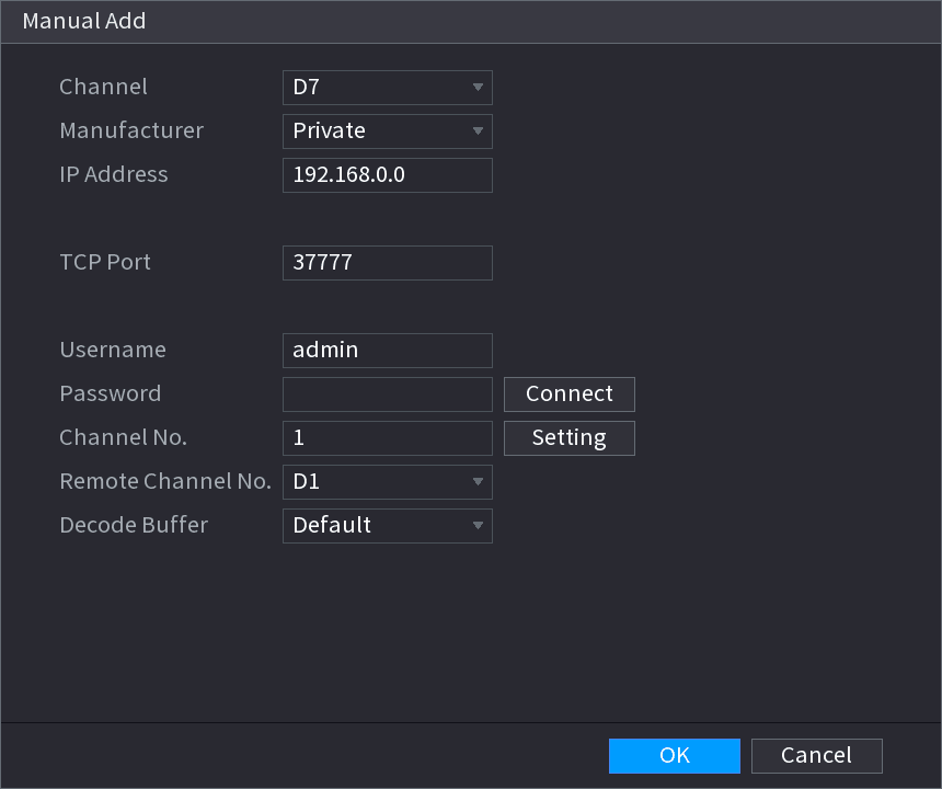
- Configure parameters. See Table 4-8.
| Parameter | Description |
|---|---|
| Channel | In the Channel list, select the channel that you want use on the Device to connect the remote device. |
| Manufacturer | In the Manufacturer list, select the manufacturer of the remote device. |
| IP Address | In the IP Address box, enter the IP address of remote device. The default is 192.168.0.0 which the system cannot connect to. |
| RTSP Port | The default value setting is 554. You can enter the value according to your actual situation. |
| HTTP Port | The default value setting is 80. You can enter the value according to your actual situation. If you enter other value, for example, 70, and then you should enter 70 after the IP address when logging in the Device by browser. |
| User Name | Enter the user name of the remote device. |
| Password | Enter the password of the user for the remote device. |
| Remote Channel | Enter the remote channel number of the remote device that you want to add. |
| Decoder Buffer | In the Decoder Buffer list, select Default, Realtime, or Fluent. |
| Protocol Type | If the remote device is added through private protocol, the default type is TCP. If the remote device is added through Onvif protocol, the system supports Auto, TCP, UDP, or MULTICAST. If the remote device is added through other manufacturers, the system supports TCP and UDP. |
| Encrypt | If the remote device is added through Onvif protocol, selecting the Encrypt check box will provide encryption protection to the data being transmitted. To use this function, the HTTPS function should be enabled for the remote IP camera. |
- Click OK. The remote device information is displayed on the Added Device list.
Complete the registration
Click Next to complete the remote device registration.
Click the edit icon to change the remote device information. Click the delete icon to delete remote device.
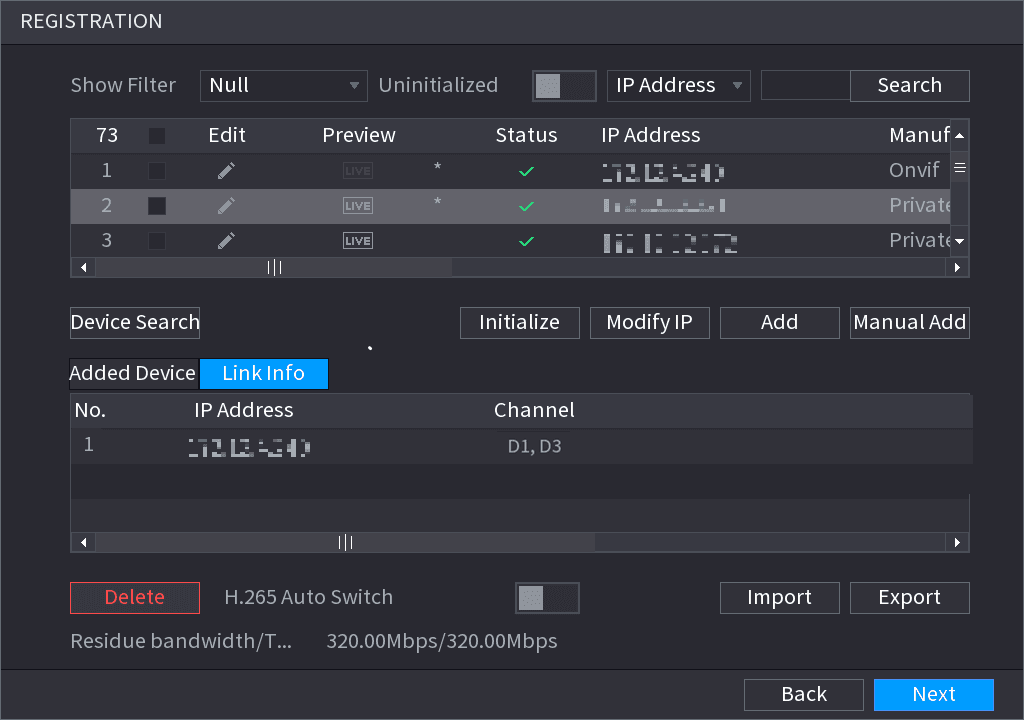
Once the multiple-sensor device has registered to the device system displays the channel status on the Link info. See Figure 4-30. It shows one remote device has occupied two channels: D1, D3.
RAID Manager
RAID (redundant array of independent disks) is a data storage virtualization technology that combines multiple physical HDD components into a single logical unit for the purposes of data redundancy, performance improvement, or both.
RAID function is for some series product only. Slight difference may be found on the user interface.
Open the RAID interface
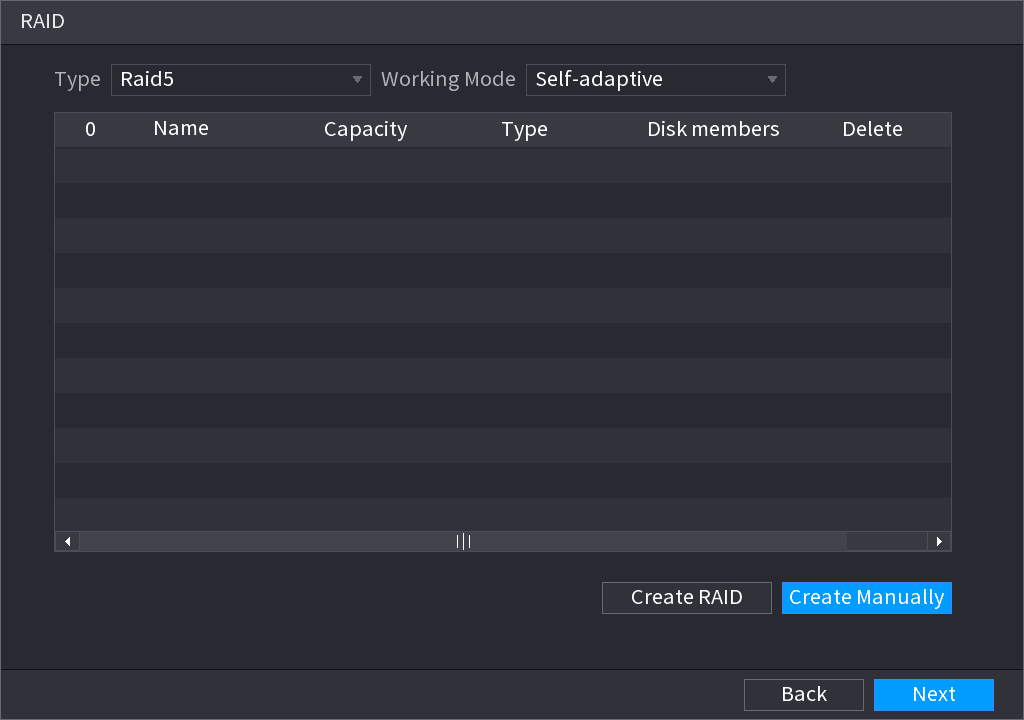
Select Main Menu > STORAGE > RAID > RAID. The RAID interface is displayed. See Figure 4-31.
Create RAID
You can click Create RAID or Create Manually, and all the disks involved will be formatted.
- Click Create RAID, the system will create RAID automatically.
- If there is no existing RAID and no hot spare disk, the system will create RAID5 and a hot spare disk automatically.
- If there is no existing RAID, but existing hot spare disk, the system will only create RAID5 and use the existing hot spare disk automatically.
- If there is existing RAID and existing hot spare disk, the system will delete the original RAID and create RAID5 with all the disks and use the existing hot spare disk automatically.
- Click Create Manually.
- Select RAID type and disks as system instructed.
- Click Create Manually, and then the format disk notice is displayed.
- Click OK.
Select working mode
After creating RAID, the disks need to sync with each other to finish the process. For RAID5 and RAID6, you can select different working mode.
- Self-Adaptive: Automatically adjust the RAID sync speed according to the business status. When there is no business running, sync is performed at a high speed. When there is business running, sync is performed at a low speed.
- Sync First: Resource priority is assigned to RAID sync.
- Business First: Resource priority is assigned to business operations.
- Balance: Resource is evenly distributed to RAID sync and business operations.
Schedule
After set record schedule and snapshot schedule, the device can automatically record video and snapshot image at the specified time. Select Main menu > STORAGE > SCHEDULE, you can go to the SCHEDULE interface.
Recording Schedule
After set schedule record, device can record video file according to the period you set here. For example, the alarm record period is from 6:00–18:00 Monday, device can record alarm video files during the 6:00–18:00.
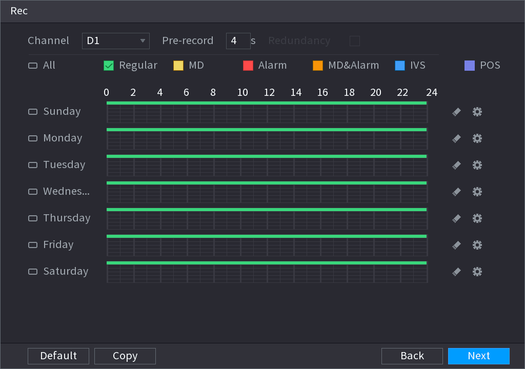
All channels are record continuously by default. You can set customized record period and record type.
Select a channel and set parameters
Select a channel from the dropdown list, you can set different record plans for different channels. Select All if you want to set for all channels. See Table 4-9.
| Parameter | Description |
|---|---|
| Channel | In the Channel list, select a channel to record the video. |
| Pre-record | In the Pre-record list, enter the amount of time that you want to start the recording in advance. |
| Redundancy | If there are several HDDs installed to the Device, you can set one of the HDDs as the redundant HDD to save the recorded files into different HDDs. In case one of the HDDs is damaged, you can find the backup in the other HDD. Select Main Menu > STORAGE > HDD MANAGER, and then set a HDD as redundant HDD. Select Main Menu > STORAGE > SCHEDUE > Record, and then select the Redundancy check box. If the selected channel is not recording, the redundancy function takes effect next time you record no matter you select the check box or not. If the selected channel is recording, the current recorded files will be packed, and then start recording according to the new schedule. This function is for some series products only. The redundant HDD only back up the recorded videos but not snapshots. |
| ANR | You can set ANR (auto network resume) function. The IPC continues record once the NVR and IPC connection fails. After the network becomes normal, the NVR can download record file during the offline period from the IPC. It is to guarantee there is no record loss on current connected IPC channel. Set the max. record upload period. Once the offline period is longer than the period you set here, IPC can only upload the record file during the specified period. This function is for IPC that installed SD card and the record function is enabled. |
| Period | Define a period during which the configured recording setting is active. See Figure 4-33. The system only activates the alarm in the defined period. |
| Copy | Click Copy to copy the settings to other channels. |
Set record type
Set record type. See Figure 4-34.

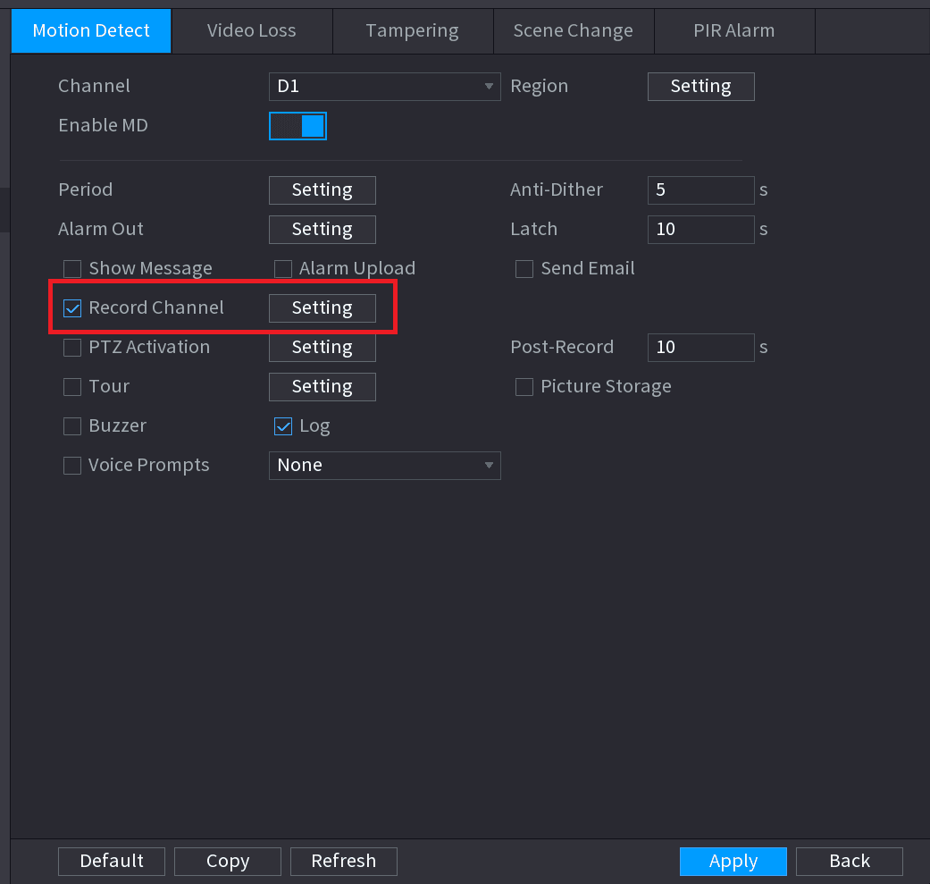
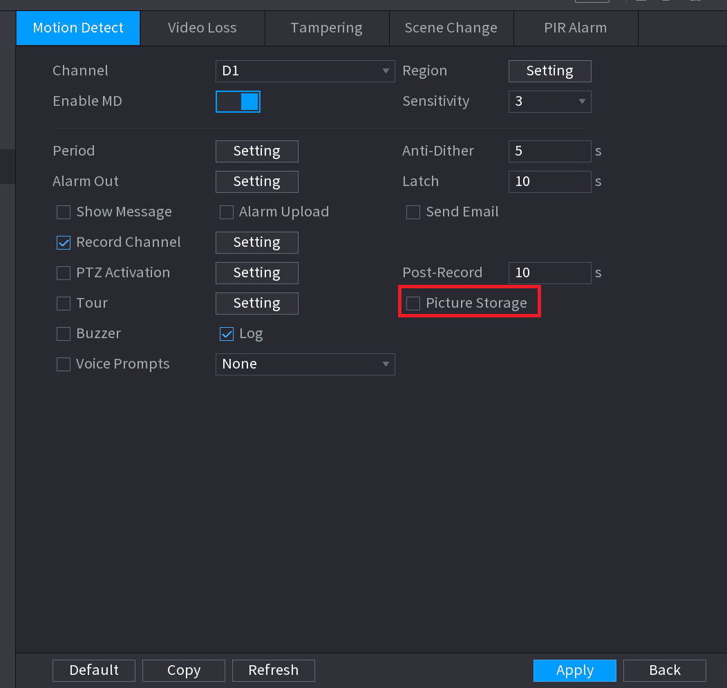
- When the record type is MD (motion detect), alarm, MD&Alarm, IVS and POS, enable the channel record function when corresponding alarm occurs. For example, when the alarm type is MD, select Main Menu > ALARM > VIDEO DETECTION > Motion Detect, select the record channel and enable record function. See Figure 4-35.
- When the record type is MD (motion detect), alarm, MD&Alarm, IVS and POS, refer to 4.8.5 Video detect, 4.8.3 Alarm, 4.7.2.4 IVS and Step 3 POS for detailed information.
Set record period
Set record period. It includes edit mode and draw mode. See Figure 4-36.
If you have added a holiday, you can set the record period for the holiday.
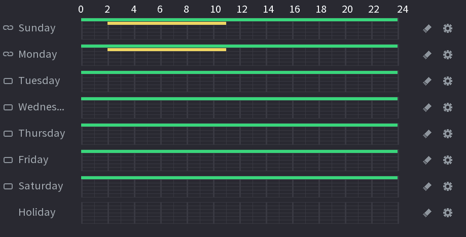
Define the period by drawing.
- Select a corresponding date to set.
- Define for the whole week: Click the link icon next to All, all the icon switches to the linked state, you can define the period for all the days simultaneously.
- Define for several days of a week: Click the icon before each day one by one, the icon switches to the linked state. You can define the period for the selected days simultaneously.
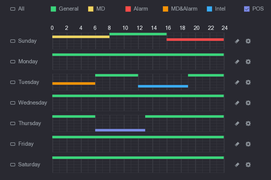
- On the timeline, left click mouse and then drag to define a period. There are six periods in one day, the Device starts recoding the selected event type in the defined period. In Figure 4-37, the different color bars stand for different record types.
- Green stands for general record.
- Yellow stands for MD (motion detection) record.
- Red stands for alarm record.
- Blue stands form intelligent record.
- Orange stands for MD&Alarm record.
- Purple stands for POS record.
- Once the time period overlaps, the record priority: MD&Alarm > Alarm > POS > Intelligent > MD > General.
- Select a record type and then click the eraser icon of the corresponding date to clear the corresponding period.
The MD record and alarm record function are both null if you enabled MD&Alarm function.
Define the period by editing.
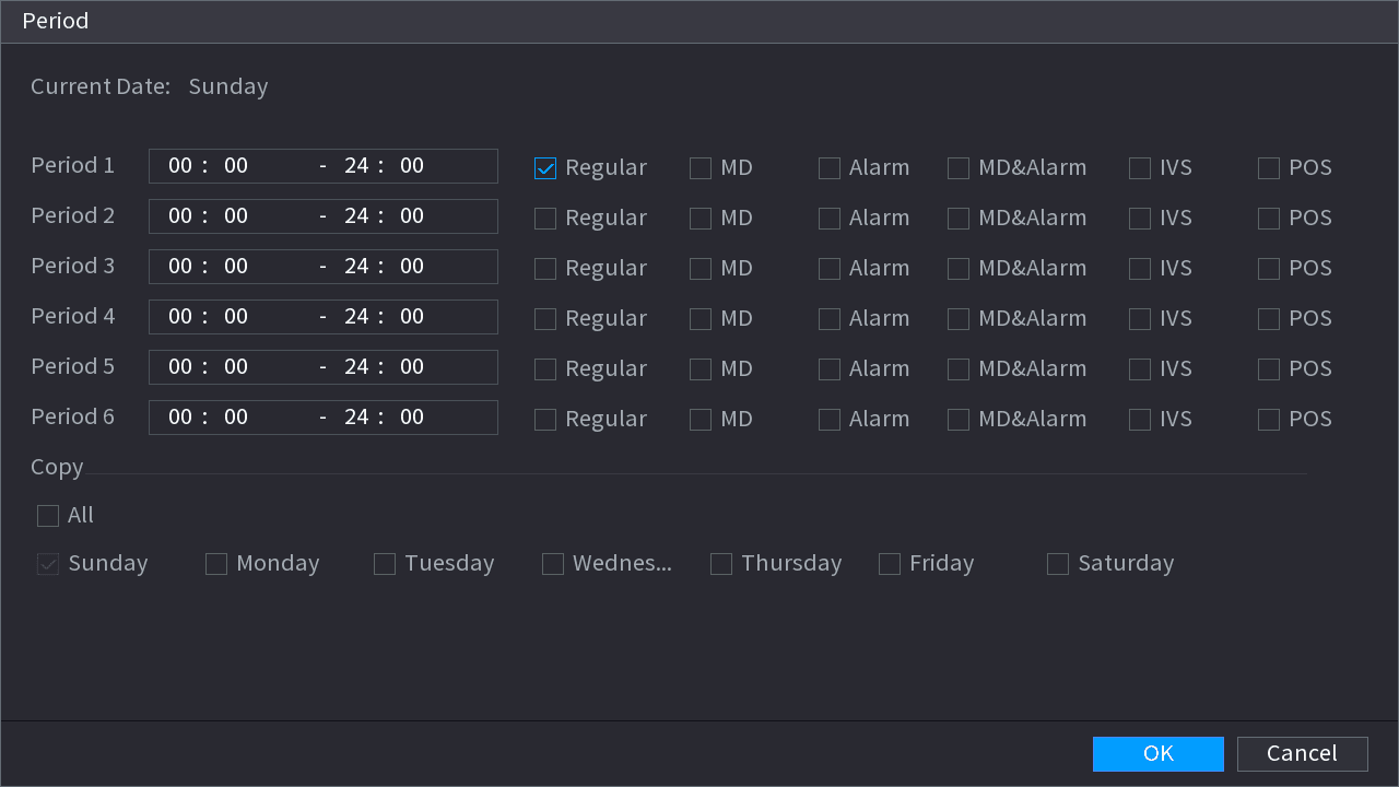
- Select a date and then click the settings icon. The Period interface is displayed. See Figure 4-38.
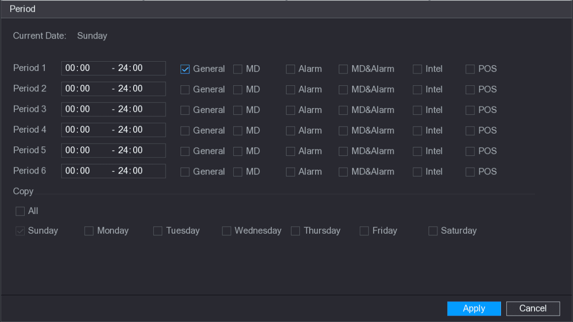
- Set record type for each period.
- There are six periods for you to set for each day.
- Under Copy, select All to apply the settings to all the days of a week, or select specific day(s) that you want to apply the settings to.
- Click Apply to save the settings.
Complete the settings
Click Apply to complete the settings.
Enable auto record function so that the record plan can become activated. Refer to 4.1.4.6.3 Record control for detailed information.
Snapshot Schedule
You can set schedule snapshot period.
After set schedule snapshot, device can snapshot image according to the period you set here. For example, the alarm snapshot period is from 6:00–18:00 Monday, device can snapshot during the 6:00–18:00 when an alarm occurs.
Open the Snapshot interface
Click Snapshot button, device goes to following interface. See Figure 4-39.
Select Main Menu > STORAGE > SCHEDULE > Snapshot, you can go to the snapshot interface.
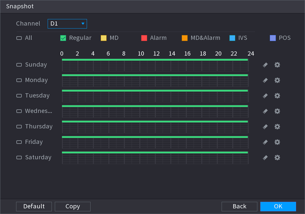
Select a channel
Select a channel to set schedule snapshot.
Set snapshot type
Set snapshot type as schedule. Refer to 4.2.5.2 Snapshot for detailed information.
Set alarm type
Check the box to set alarm type. See Figure 4-40.

- When the record type is MD (motion detect), alarm, MD&Alarm, IVS and POS, enable the channel record function when corresponding alarm occurs. For example, when the alarm type is MD, select Main Menu > ALARM > VIDEO DETECTION > Motion Detect, select the record channel and enable record function. See Figure 4-35.
- When the record type is MD (motion detect), alarm, MD&Alarm, IVS and POS, refer to 4.8.5 Video detect, 4.8.3 Alarm, 4.7.2.4 IVS and Step 3 POS for detailed information.
Set snapshot period
Refer to 4.1.4.6.1 Record to set snapshot period.
Save the snapshot plan
Click Apply button to save snapshot plan.
Enable auto snapshot function so that the snapshot plan can become activated. Refer to 4.1.4.6.3 Record control for detailed information.
Record Control
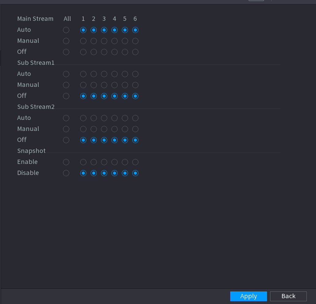
After set schedule record or schedule snapshot, you need to enable auto record and snapshot function so that system can automatically record or snapshot.
- Auto: System automatically records at the type and record period you set in Schedule interface.
- Manual: System records general files for all day.
You need to have storage authorities to implement the Manual record operation. Make sure the HDD has been properly installed.
Open the Record interface
Right click mouse and then select Manual > Record or select Main Menu > STORAGE > RECORD. See Figure 4-42.
For some series products, after you logged in, you can click the Rec button at the front panel to go to the Record interface.
Configure parameters
Configure parameters.
| Parameter | Description |
|---|---|
| Channel | Displays all the analog channels and the connected digital channels. You can select a single channel or select All. |
| Record status | Auto: Automatically record according to the record type and recording time as configured in the recording schedule. Manual: Keep general recording for 24 hours for the selected channel. Off: Do not record. |
| Snapshot status | Enable or disable the scheduled snapshot for the corresponding channels. |
Apply the settings
Click Apply.
Getting Started
Boot up the LTS Sapphire NVR and complete device initialization — set the time zone, create the admin password, configure the unlock pattern, and set up password protection.
Camera
Register and manage remote network cameras on the Sapphire NVR, including changing IP addresses, importing and exporting device lists, remote device initialization, image, encode and snapshot settings, channel name, remote upgrade, and remote device status and firmware information.