 Centar za pomoć LTS Connect
Network Management
Configure the Sapphire Series CVI DVR network settings including TCP/IP, ports, Wi-Fi, 3G/4G, PPPoE, DDNS, UPnP, email, SNMP, multicast, alarm center, register, P2P, 802.1x, and run network connection tests and packet capture.
Configuring Network Settings
You can ensure the network interworking between the Device and other devices through configuring the network settings.
Configuring TCP/IP Settings
You can configure the settings for the Device such as IP address, DNS according to the networking plan.
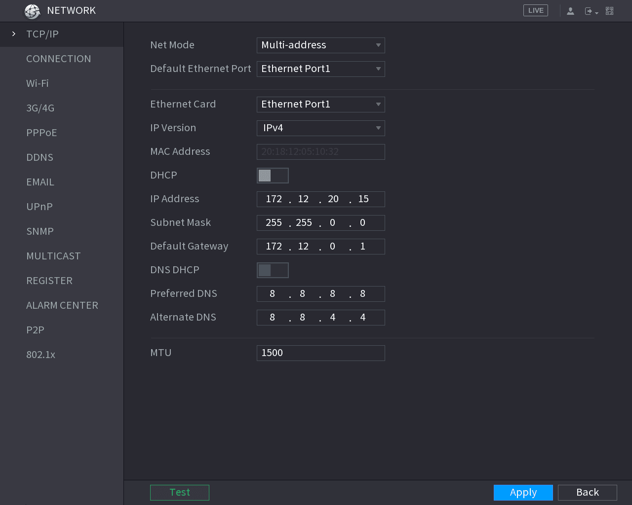
Select Main Menu > NETWORK > TCP/IP, the TCP/IP interface is displayed. See Figure 5-196. For details about parameter settings, see "5.1.4.4 Configuring Network Settings."
Configuring Port Settings
You can configure the maximum connection accessing the Device from Client such as WEB, Platform, and Mobile Phone and configure each port settings.
Open the CONNECTION interface
Select Main Menu > NETWORK > CONNECTION.
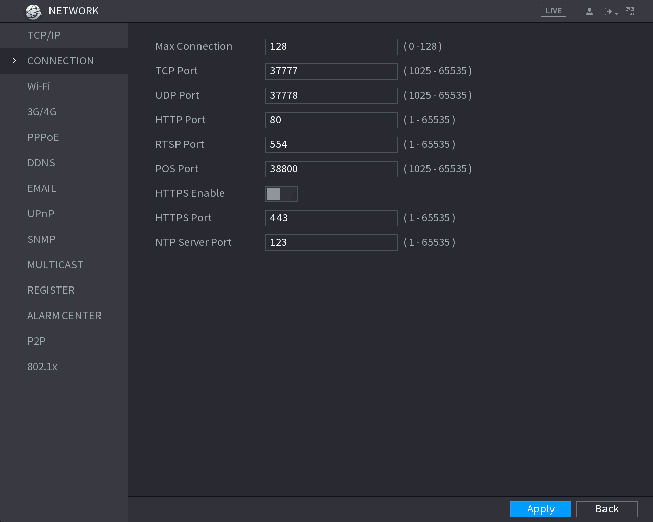
The CONNECTION interface is displayed. See Figure 5-197.
Configure the connection parameters
Configure the settings for the connection parameters. See Table 5-59.
The parameter setting can take effect without need to reboot the device.
| Parameter | Description |
|---|---|
| Max Connection | The allowable maximum clients accessing the Device at the same time, such as WEB, Platform, and Mobile Phone. Select a value between 1 and 128. The default value setting is 128. |
| TCP Port | The default value setting is 37777. You can enter the value according to your actual situation. |
| UDP Port | The default value setting is 37778. You can enter the value according to your actual situation. |
| HTTP Port | The default value setting is 80. You can enter the value according to your actual situation. If you enter other value, for example, 70, and then you should enter 70 after the IP address when logging in the Device by browser. |
| RTSP Port | The default value setting is 554. You can enter the value according to your actual situation. |
| POS Port | Data transmission. The value range is from 1 through 65535. The default value is 38800. |
| HTTPS Enable | Enable HTTPS. |
| HTTPS Port | HTTPS communication port. The default value setting is 443. You can enter the value according to your actual situation. |
Apply the settings
Click Apply to complete the settings.
Configuring Wi-Fi Connection Settings
You can make wireless connection between the Device and the other devices in the same network through Wi-Fi settings, facilitating the devices connection and mobility.
Only the Device with Wi-Fi module supports this function.
Open the Wi-Fi interface
Select Main Menu > NETWORK > Wi-Fi.
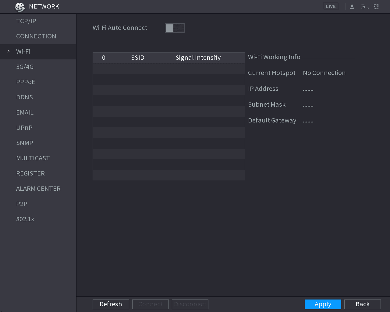
The Wi-Fi interface is displayed. See Figure 5-198.
Configure the Wi-Fi connection parameters
Configure the settings for the Wi-Fi connection parameters. See Table 5-60.
| Parameter | Description |
|---|---|
| Wi-Fi Auto Connect | Enable Wi-Fi Auto Connect. After the Device is restarted, it will automatically connect to the nearest hotspot that had been connected successfully. |
| Refresh | Refresh the hotspot list. The self-adaption function such as adding password is supported if such setting was once configured. |
| Connect | In the hotpots list, select a hotspot, and then click Connect. • To reconnect the same hotspot, disconnect first and then reconnect. • To connect to other hotspot, disconnect from the current connected hotspot first, and then connect to the other hotspot. |
| Disconnect | To disconnect from a hotspot, click Disconnect. |
Apply the settings
Click Apply to complete the settings.
After the Device is connected to a Wi-Fi hotspot, in the Wi-Fi Working Info area, the current hotspot, IP address, subnet mask, and default gateway are displayed.
Configuring 3G/4G Settings
You can connect a wireless 3G/4G module to the USB port of the Device and then access the Device with the IP address provided by the module.
Not all models support this function.
Connect the wireless module
Connect the wireless 3G/4G module to the USB port of the Device.
Open the 3G/4G interface
Select Main Menu > NETWORK > 3G/4G.
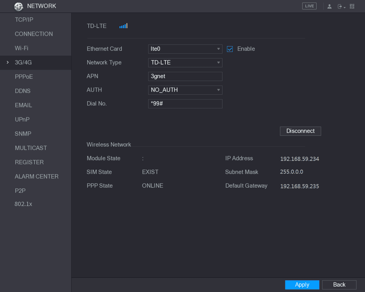
The 3G/4G interface is displayed, see Figure 5-199.
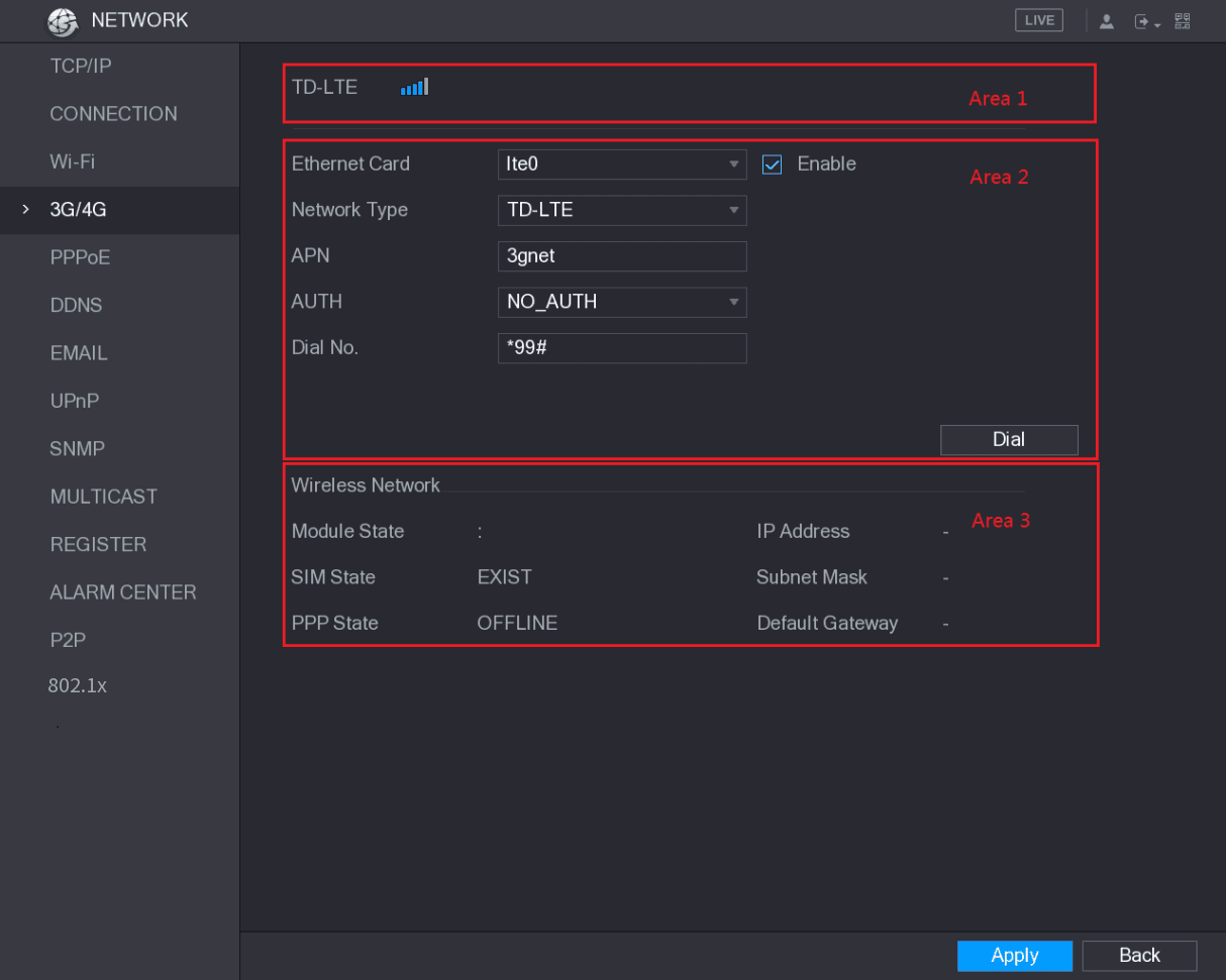
The 3G/4G interface is consisted of three areas:
- Area 1: Displays the signal strength.
- Area 2: Displays the module configurations.
- Area 3: Displays the connection state.
The information of Area 2 will display after the 3G/4G module is connected; while the information of Area 1 and Area 3 will display only after the 3G/4G function is enabled.
The Device starts identifying the wireless module and displays the recognized information for the parameters in Area 2. See Table 5-61.
| Parameter | Description |
|---|---|
| Ethernet Card | Displays the name of Ethernet card. |
| Network Type | Displays the network type. Different type represents different supplier. |
| APN | Displays the default APN number. |
| Dial No. | Displays the default dial No. |
| AUTH | Authentication mode. You can select PAP, CHAP, or NO_AUTH. |
Verify the connection
After the connection is established, the result is displayed in the Wireless Network area. See Figure 5-200.
Apply the settings
Click Apply to complete the settings.
Supported 3G/4G Modules by the Device
- China Mobile 3G/4G: ZTE MF832S
- China Mobile 4G: ZTE MF832S
- China Unicom 3G: ZTE MF667S, HUAWEI E353U-1
- China Telecom 4G: HUAWEI EC122, ZTE AC2736
- If the Device is connected to China Telecom 3G/4G network, you can login the Device with the public IP address through the PC of public internet (The HTTP port is not configured as 80). If the Device is connected to China Unicom or China Mobile 3G network, which are defined as private network, therefore you cannot login the Device through PC that is connected to public internet.
- The Ethernet card names that are displayed on the 3G/4G interface are not constant, and they could be ppp5, ppp6, ppp7 or ppp8 and are different depending on the USB2.0 port on the Device that is connected to the 3G module.
- If you dial to connect to 3G/4G network, you have to keep trying till succeeded. The default gateway could be switched depending on the priority of Ethernet cards.
- The China Unicom and China Mobile 3G/4G modules in USB flash disk style do not support EDGE mode for the moment.
Configuring PPPoE Settings
PPPoE is another way for the Device to access the network. You can establish network connection by configuring PPPoE settings to give the Device a dynamic IP address in the WAN. To use this function, firstly you need to obtain the user name and password from the Internet Service Provider.
Open the PPPoE interface
Select Main Menu > NETWORK > PPPoE.
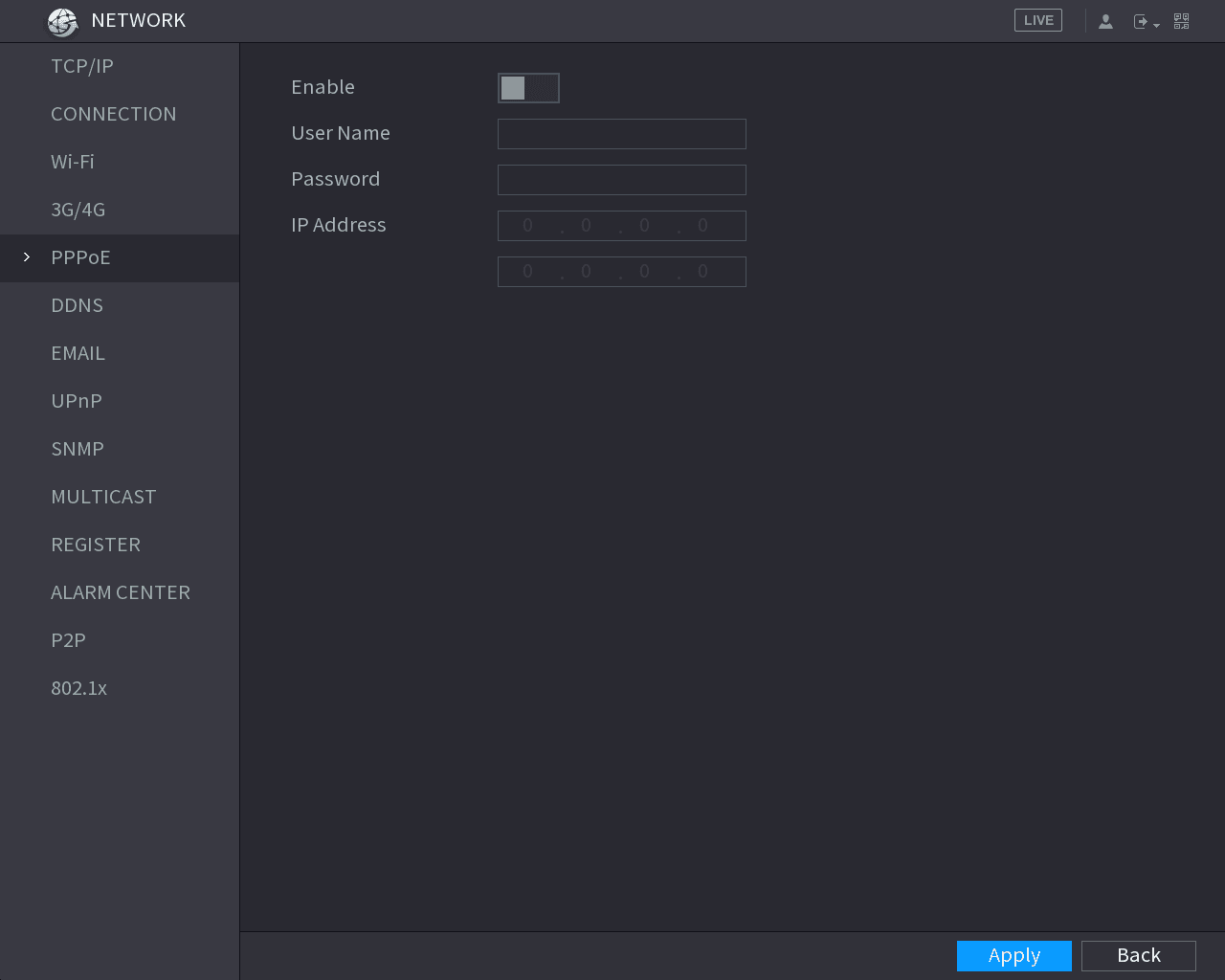
The PPPoE interface is displayed. See Figure 5-201.
Enable PPPoE and enter credentials
Enable the PPPoE function.
In the User Name box and Password box, enter the user name and password accordingly provided by the Internet Service Provider.
Apply the settings
Click Apply to complete the settings.
The system pops up a message to indicate the successfully saved. The IP address appears on the PPPoE interface. You can use this IP address to access the Device.
When the PPPoE function is enabled, the IP address on the TCP/IP interface cannot be modified.
Configuring DDNS Settings
When the IP address of the Device changes frequently, the DDNS function can dynamically refresh the correspondence between the domain on DNS and the IP address, ensuring you access the Device by using the domain.
Preparing for Configuration
Please confirm if the Device supports the DDNS Type and log in the website provided by the DDNS service provider to register the information such as domain from PC located in the WAN.
After you have registered and logged in the DDNS website successfully, you can view the information of all the connected devices under this user name.
Configuring Steps
Open the DDNS interface
Select Main Menu > NETWORK > DDNS.
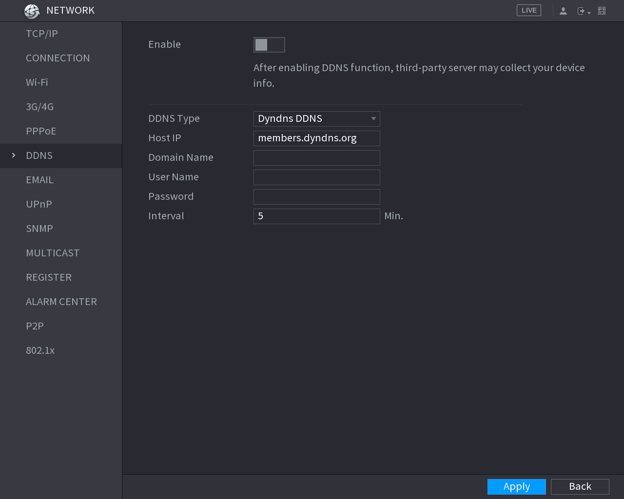
The DDNS interface is displayed. See Figure 5-202.
Configure the DDNS parameters
Configure the settings for the DDNS parameters. See Table 5-62.
| Parameter | Description |
|---|---|
| Enable | Enable the DDNS function. After enabling DDNS function, the third-party might collect your Device information. |
| DDNS Type Host IP | Type and address of DDNS service provider. • Type: Dyndns DDNS; address: members.dyndns.org • Type: NO-IP DDNS; address: dynupdate.no-ip.com • Type: CN99 DDNS; address: members.3322.org |
| Domain Name | The domain name for registering on the website of DDNS service provider. |
| User Name Password | Enter the user name and password obtained from DDNS service provider. You need to register (including user name and password) on the website of DDNS service provider. |
| Interval | Enter the amount of time that you want to update the DDNS. |
Apply and verify
Click Apply to complete the settings.
Enter the domain name in the browser on your PC, and then press Enter.
If the web interface of the Device is displayed, the configuration is successful. If not, the configuration is failed.
Configuring EMAIL Settings
You can configure the email settings to enable the system to send the email as a notification when there is an alarm event occurs.
Open the EMAIL interface
Select Main Menu > NETWORK > EMAIL.
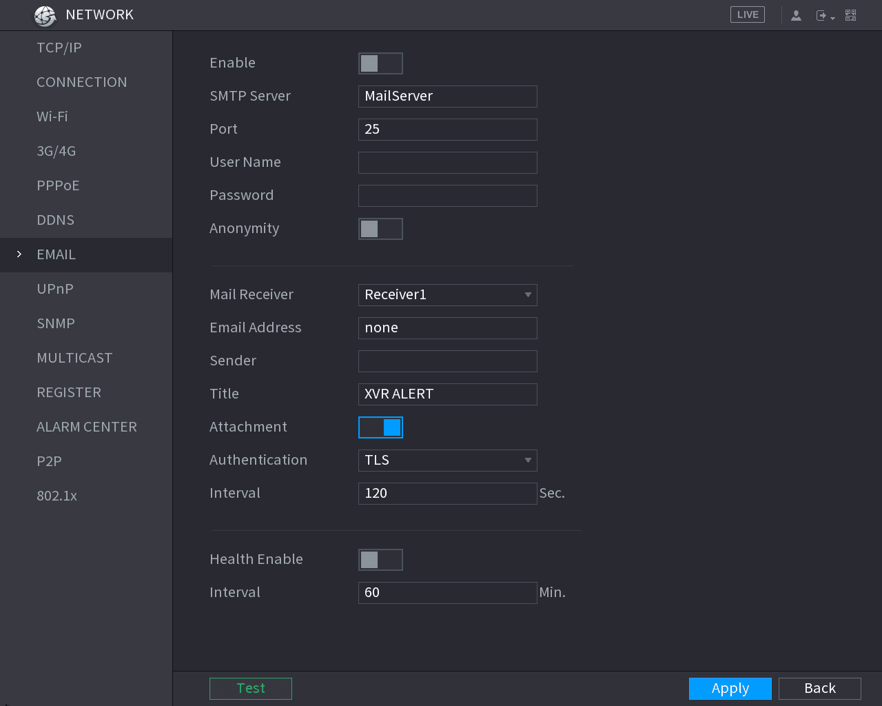
The EMAIL interface is displayed. See Figure 5-203.
Configure the email parameters
Configure the settings for the email parameters. See Table 5-63.
| Parameter | Description |
|---|---|
| Enable | Enable the email function. |
| SMTP Server | Enter the address of SMTP server of sender's email account. |
| Port | Enter the port value of SMTP server. The default value setting is 25. You can enter the value according to your actual situation. |
| User Name Password | Enter the user name and password of sender's email account. |
| Anonymity | If enable the anonymity function, you can login as anonymity. |
| Mail Receiver | In the Mail Receiver list, select the number of receiver that you want to receive the notification. The Device supports up to three mail receivers. |
| Email Address | Enter the email address of mail receiver(s). |
| Sender | Enter the sender's email address. It supports maximum three senders separated by comma. |
| Title | Enter the email subject. Supports Chinese, English and Arabic numerals. It supports maximum 64 characters. |
| Attachment | Enable the attachment function. When there is an alarm event, the system can attach snapshots as an attachment to the email. |
| Authentication | Select the encryption type: NONE, SSL, or TLS. For SMTP server, the default encryption type is TLS. |
| Interval (Sec.) | This is the interval that the system sends an email for the same type of alarm event, which means, the system does not send an email upon any alarm event. This setting helps to avoid the large amount of emails caused by frequent alarm events. The value ranges from 0 to 3600. 0 means that there is no interval. |
| Health Enable | Enable the health test function. The system can send a test email to check the connection. |
| Interval (Min.) | This is the interval that the system sends a health test email. The value ranges from 30 to 1440. 0 means that there is no interval. |
| Test | Click Test to test the email sending function. If the configuration is correct, the receiver's email account will receive the email. Before testing, click Apply to save the settings. |
Apply the settings
Click Apply to complete the settings.
Configuring UPnP Settings
You can map the relationship between the LAN and the WAN to access the Device on the LAN through the IP address on the WAN.
Preparation for Configuration
- Login the router to set the WAN port to enable the IP address to connect into the WAN.
- Enable the UPnP function at the router.
- Connect the Device with the LAN port on the router to connect into the LAN.
- Select Main Menu > NETWORK > TCP/IP, configure the IP address into the router IP address range, or enable the DHCP function to obtain an IP address automatically.
Configuration Steps
Open the UPnP interface
Select Main Menu > NETWORK > UPnP.
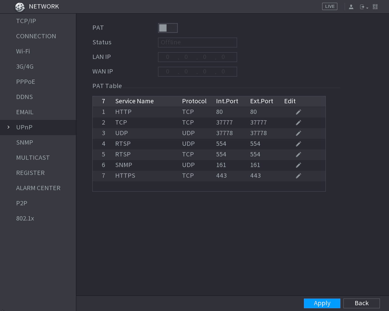
The UPnP interface is displayed. See Figure 5-204.
Configure the UPnP parameters
Configure the settings for the UPnP parameters. See Table 5-64.
| Parameter | Description |
|---|---|
| PAT | Enable the UPnP function. |
| Status | Indicates the status of UPnP function. • Offline: Failed. • Online: Succeeded. |
| LAN IP | Enter IP address of router on the LAN. After mapping succeeded, the system obtains IP address automatically without performing any configurations. |
| WAN IP | Enter IP address of router on the WAN. After mapping succeeded, the system obtains IP address automatically without performing any configurations. |
| PAT Table | The settings in PAT table correspond to the UPnP PAT table on the router. • Service Name: Name of network server. • Protocol: Type of protocol. • Int. Port: Internal port that is mapped on the Device. • Ext. Port: External port that is mapped on the router. • To avoid the conflict, when setting the external port, try to use the ports from 1024 through 5000 and avoid popular ports from 1 through 255 and system ports from 256 through 1023. • When there are several devices in the LAN, please reasonably arrange the ports mapping to avoid mapping to the same external port. • When establishing a mapping relationship, please ensure the mapping ports are not occupied or limited. • The internal and external ports of TCP and UDP must be the same and cannot be modified. • Click the edit icon to modify the external port. |
Apply and access
Click Apply to complete the settings.
In the browser, enter http://WAN IP: External IP port. You can visit the LAN Device.
Configuring SNMP Settings
Not all models support this function.
You can connect the Device with some software such as MIB Builder and MG-SOFT MIB Browser to manage and control the Device from the software.
Preparation for Configuration
- Install the software that can manage and control the SNMP, such as MIB Builder and MG-SOFT MIB Browser
- Obtain the MIB files that correspond to the current version from the technical support.
Configuration Steps
Open the SNMP interface
Select Main Menu > NETWORK > SNMP.
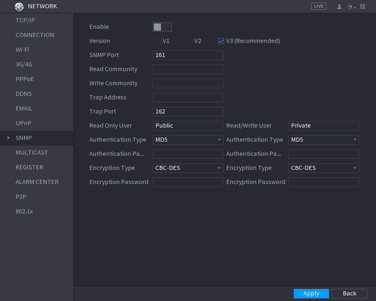
The SNMP interface is displayed. See Figure 5-205.
Configure the SNMP parameters
Configure the settings for the SNMP parameters. See Table 5-65.
| Parameter | Description |
|---|---|
| Enable | Enable the SNMP function. |
| Version | Select the check box of SNMP version(s) that you are using. The default version is V3. There is a risk of select V1 or V2. |
| SNMP Port | Indicates the monitoring port on the agent program. |
| Read Community Write Community | Indicates the read/write strings supported by the agent program. |
| Trap Address | Indicates the destination address for the agent program to send the Trap information. |
| Trap Port | Indicates the destination port for the agent program to send the Trap information. |
| Read Only User | Enter the user name that is allowed to access the Device and has the "Read Only" permission. |
| Read/Write User | Enter the user name that is allowed to access the Device and has the "Read and Write" permission. |
| Authentication Type | Includes MD5 and SHA. The system recognizes automatically. |
| Authentication Password Encryption Password | Enter the password for authentication type and encryption type. The password should be no less than eight characters. |
| Encryption Type | In the Encryption Type list, select an encryption type. The default setting is CBC-DES. |
Compile the MIB files
Compile the two MIB files by MIB Builder.
Load the module in MG-SOFT MIB Browser
Run MG-SOFT MIB Browser to load in the module from compilation.
Query the Device
On the MG-SOFT MIB Browser, enter the Device IP that you want to manage, and then select the version number to query.
Obtain the configurations
On the MG-SOFT MIB Browser, unfold the tree-structured directory to obtain the configurations of the Device, such as the channels quantity and software version.
Configuring Multicast Settings
When you access the Device from the network to view the video, if the access is exceeded, the video will not display. You can use the multicast function to group the IP to solve the problem.
Open the MULTICAST interface
Select Main Menu > NETWORK > MULTICAST.
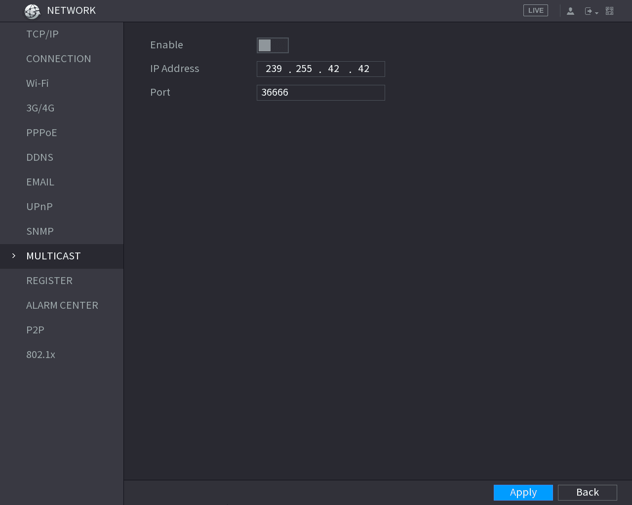
The MULTICAST interface is displayed. See Figure 5-206.
Configure the multicast parameters
Configure the settings for the multicast parameters. See Table 5-66.
| Parameter | Description |
|---|---|
| Enable | Enable the multicast function. |
| IP Address | Enter the IP address that you want to use as the multicast IP. The IP address ranges from 224.0.0.0 through 239.255.255.255. |
| Port | Enter the port for the multicast. The port ranges from 1025 through 65000. |
Apply the settings
Click Apply to complete the settings.
Login the web by multicast
You can use the multicast IP address to login the web. See Figure 5-207.
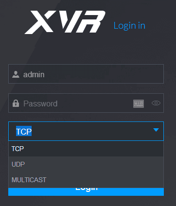
On the web login dialog box, in the Type list, select MULTICAST. The web will automatically obtain the multicast IP address and join. Then you can view the video through multicast function.
Configuring Register Settings
You can register the Device into the specified proxy server which acts as the transit to make it easier for the client software to access the Device.
Open the REGISTER interface
Select Main Menu > NETWORK > REGISTER.
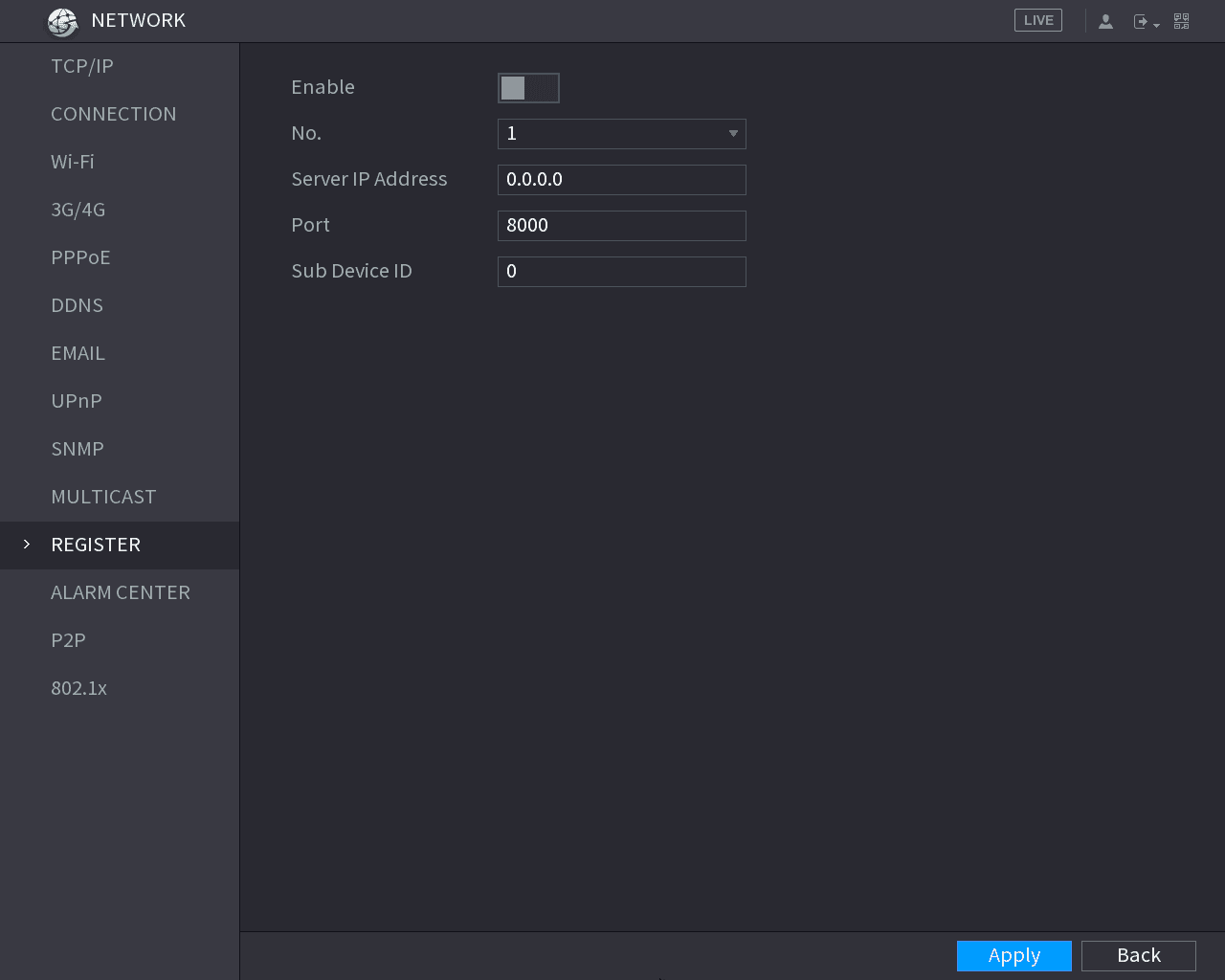
The REGISTER interface is displayed. See Figure 5-208.
Configure the register parameters
Configure the settings for the register parameters. See Table 5-67.
| Parameter | Description |
|---|---|
| Enable | Enable the register function. |
| Server IP Address | Enter the server IP address or the server domain that you want to register to. |
| Port | Enter the port of the server. |
| Sub Service ID | This ID is allocated by the server and used for the Device. |
Apply the settings
Click Apply to complete the settings.
Configuring Alarm Center Settings
You can configure the alarm center server to receive the uploaded alarm information. To use this function, the Alarm Upload check box must be selected. For details about alarm event settings, see "5.10 Alarm Events Settings."
Open the ALARM CENTER interface
Select Main Menu > NETWORK > ALARM CENTER.
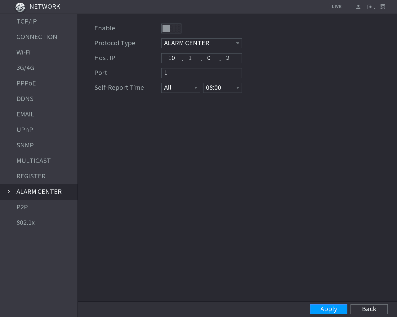
The ALARM CENTER interface is displayed. See Figure 5-209.
Configure the alarm center parameters
Configure the settings for the alarm center parameters. See Table 5-68.
| Parameter | Description |
|---|---|
| Enable | Enable the alarm center function. |
| Protocol Type | In the Protocol Type list, select protocol type. The default is ALARM CENTER. |
| Host IP Port | The IP address and communication port of the PC installed with alarm client. |
| Self-Report Time | In the Self-Report Time list, select time cycle and specific time for uploading alarm. |
Apply the settings
Click Apply to complete the settings.
Configuring P2P Settings
You can manage the devices by using P2P technology to download the application and register the devices. For details, see "5.1.4.5 Configuring P2P Settings."
802.1x
The Device can be connected with LAN after passing 802.1x certification.
Open the 802.1x interface
Select Main Menu > NETWORK > 802.1x.
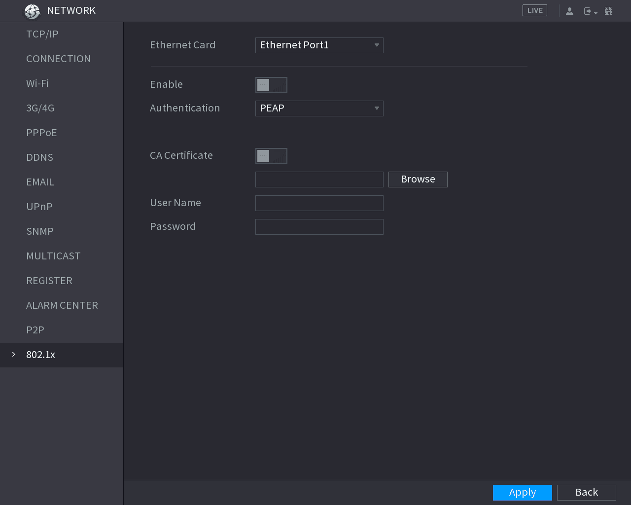
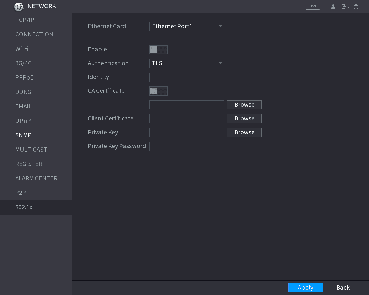
The 802.1x interface is displayed. See Figure 5-210 and Figure 5-211.
Select the Ethernet card
Select the Ethernet card you want to certify.
Enable and configure parameters
Select Enable and configure parameters. See Table 5-69.
| Parameter | Description |
|---|---|
| Authentication | • PEAP: protected EAP protocol. • TLS: Transport Layer Security. Provide privacy and data integrity between two communications application programs. |
| Identity | It can be configured when Authentication is TLS. |
| CA Certificate | Enable it and click Browse to import CA certificate from flash drive. |
| Username | The username shall be authorized at server. |
| Password | Password of the corresponding username. |
| Client Certificate Private Key | When Authentication is TLS, click Browse to import from flash drive. |
| Private Key Password | It can be configured when Authentication is TLS. |
Apply the settings
Click Apply to complete the settings.
Configuring Network Testing Settings
Testing the Network
You can test the network connection status between the Device and other devices.
Open the Network Test interface
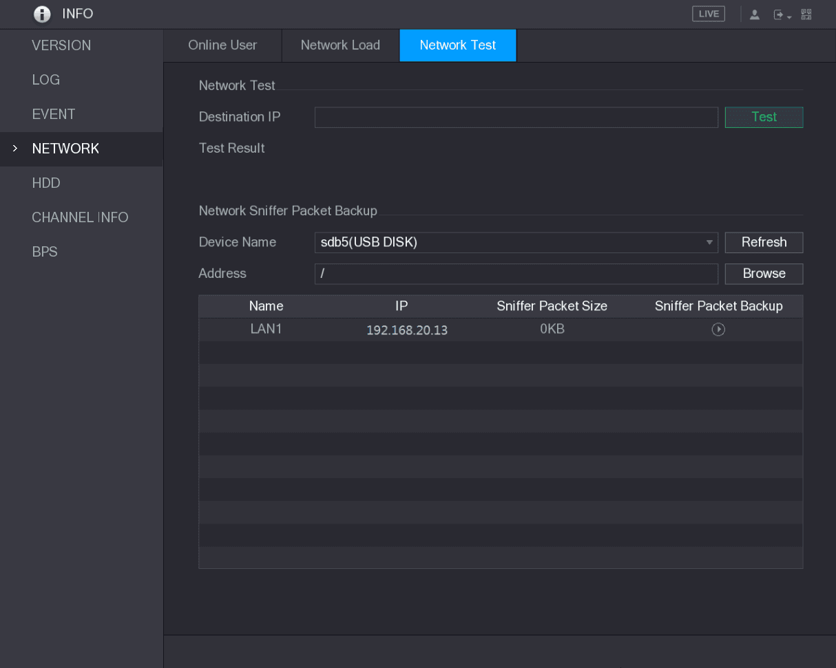
Select Main Menu > INFO > NETWORK > Network Test.
The Network Test interface is displayed. See Figure 5-212.
Enter the destination IP
In the Destination IP box, enter the IP address.
Run the test
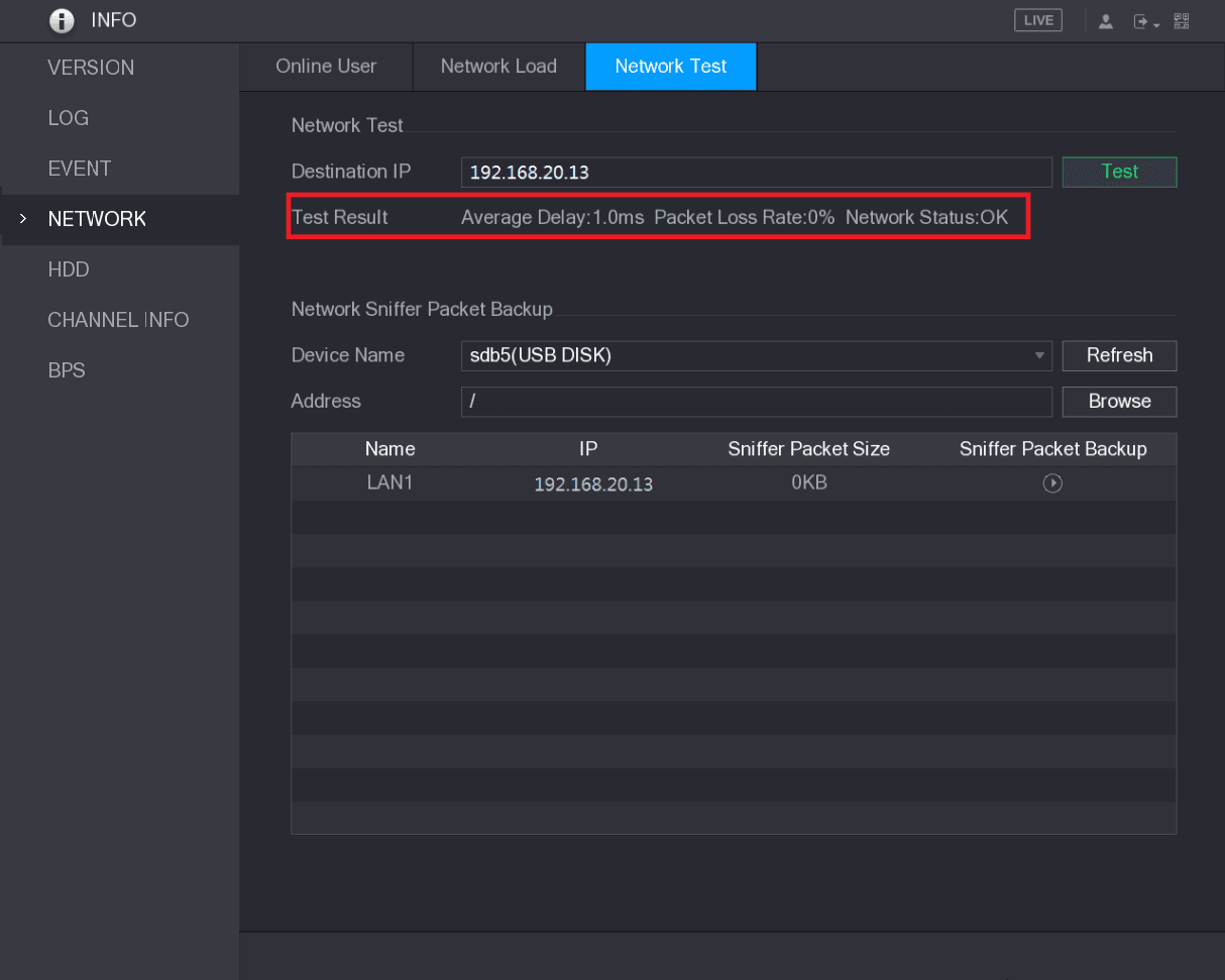
Click Test.
After testing is completed, the test result is displayed. You can check the evaluation for average delay, packet loss, and network status. See Figure 5-213.
Capturing Packet and Backing up
Packet capture means the operations such as capturing, resending, and editing data that are sent and received during network transmission. When there is network abnormality, you can perform packet capturing and back up into the USB storage device. This date can be provided to the technical support for analyzing the network condition.
Open the Network Test interface
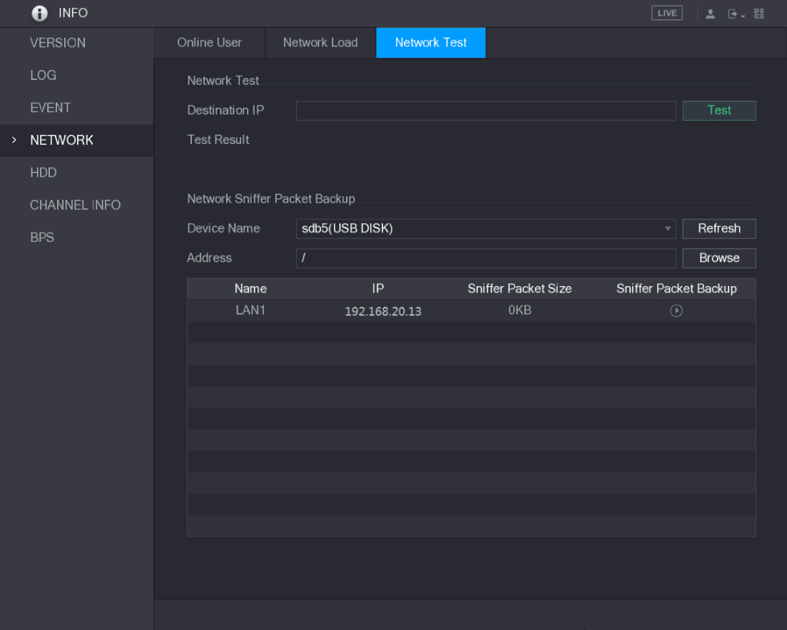
Select Main Menu > INFO > NETWORK > Network Test.
The Network Test interface is displayed. See Figure 5-214.
Connect a USB storage device
Connect a USB storage device to the Device.
Refresh and detect the device
Click Refresh.
The Device starts detecting the USB storage device and displays its name in the Device Name box.
Select the backup route
Select the route of the data that you want to capture and back up.
-
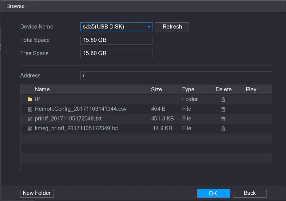
In the Network Sniffer Packet Backup area, click Browse.
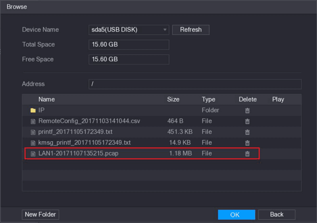
The Browse interface is displayed. See Figure 5-215.
-
Select the route.
- If there are several USB storage devices are connected to the Device, you can select from the Device Name list.
- Click Refresh to total space, free space and the file list in the selected USB storage device.
- In the case of insufficient capacity, click the delete icon to delete the needless files.
- Click New Folder to create a new folder in the USB storage device.
-
Click Apply to save the route selection settings.
The Test interface is displayed again.
Start packet capturing and backing up
Click the capture icon to start packet capturing and backing up.
- Only the data packet of one LAN can be captured at one time.
- After capturing starts, you can exit the Test interface to perform other operations such as web login and monitoring.
Stop capturing
Click the stop icon to stop capturing.
The backup data is saved in the selected route under the naming style "LAN name-time.pcap." See Figure 5-216. You can open it by using Wireshark software.
POS and Backup
How to connect the Sapphire Series CVI DVR to a POS machine, search and configure POS overlay settings, and back up recorded videos and snapshots to a USB device.
Account Settings
Add, modify, and delete user accounts, group accounts, and ONVIF users, and set security questions for the admin account on the Sapphire Series CVI DVR.