 Centro assistenza LTS Connect
The Grand Tour
A reference tour of the LTS Sapphire Series CVI DVR front and rear panels for every model, plus remote control and mouse operations.
This chapter introduces various components of the Device, remote control and mouse operations.
Front Panel
Smart 1U
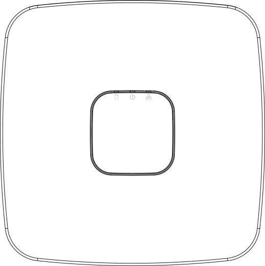
| Icon | Name | Function |
|---|---|---|
| HDD status indicator | The indicator is off when the HDD is running normally. The indicator glows blue when the HDD is in malfunction. | |
| Power status indicator | The indicator is off when the power is connected abnormally. The indicator glows blue when the power is connected normally. | |
| Network status indicator | The indicator is off when the network connection is correct. The indicator glows blue when the network connection is abnormal. |
E Model
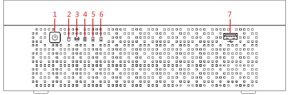
| No. | Button/Icon | Function |
|---|---|---|
| 1 | Power | Turns on/off the DVR. The indicator glows blue when the DVR is turned on. |
| 2 | HDD status indicator | The indicator glows blue when the HDD is in malfunction. |
| 3 | Network status indicator | The indicator glows blue when the network connection is abnormal. |
| 4, 5, 6 | Battery status indicator | When the battery remains full or no less than sixty percent, the No.4 indicator is on, and the No.5 and No.6 are out. When the battery remains between thirty percent and sixty percent, the No.5 indicator is on and the others are out. When the battery remains between one percent and thirty percent, the No.6 indicator is on and the others are out. When the battery is exhausted, the DVR is turned off, or there is no battery attached to the DVR, all the three indicators are out. |
| 7 | USB port | Connects to external devices such as USB storage device, keyboard, and mouse. |
Compact 1U
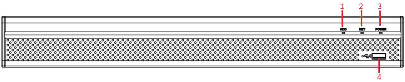
| No. | Port Name | Function |
|---|---|---|
| 1 | HDD | Glows blue when HDD status is abnormal. |
| 2 | NET | Glows blue when network status is abnormal. |
| 3 | POWER | Glows blue when the power is connected properly. |
| 4 | USB port | Connects to peripheral devices such as USB storage device, keyboard, and mouse. |
MINI 1U
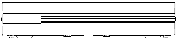
| No. | Port Name | Function |
|---|---|---|
| 1 | HDD | Glows blue when HDD status is abnormal. |
| 2 | NET | Glows blue when network status is abnormal. |
| 3 | POWER | Glows blue when the power is connected properly. |
| 4 | USB port | Connects to peripheral devices such as USB storage device, keyboard, and mouse. |
Cooper 1U
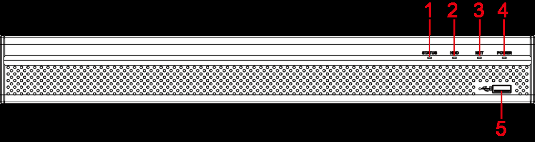
1U
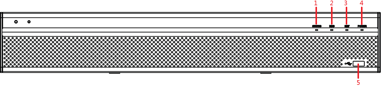
| No. | Port Name | Function |
|---|---|---|
| 1 | Status indicator light | Glows blue when the device is working properly. |
| 2 | HDD | Glows blue when HDD status is abnormal. |
| 3 | NET | Glows blue when network status is abnormal. |
| 4 | POWER | Glows blue when the power is connected properly. |
| 5 | USB port | Connects to the external devices such as keyboard, mouse, and USB storage device. |
1.5U
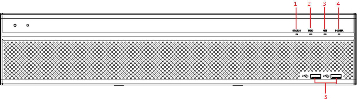
| No. | Port Name | Function |
|---|---|---|
| 1 | Status indicator light | Glows blue when the device is working properly. |
| 2 | HDD | Glows blue when HDD status is abnormal. |
| 3 | NET | Glows blue when network status is abnormal. |
| 4 | POWER | Glows blue when the power is connected properly. |
| 5 | USB port | Connects to peripheral devices such as USB storage device, keyboard, and mouse. |
2U
| No. | Port Name | Function |
|---|---|---|
| 1 | Status indicator light | Glows blue when the device is working properly. |
| 2 | HDD | Glows blue when HDD status is abnormal. |
| 3 | NET | Glows blue when network status is abnormal. |
| 4 | POWER | Glows blue when the power is connected properly. |
| 5 | USB port | Connects to peripheral devices such as USB storage device, keyboard, and mouse. |
Rear Panel
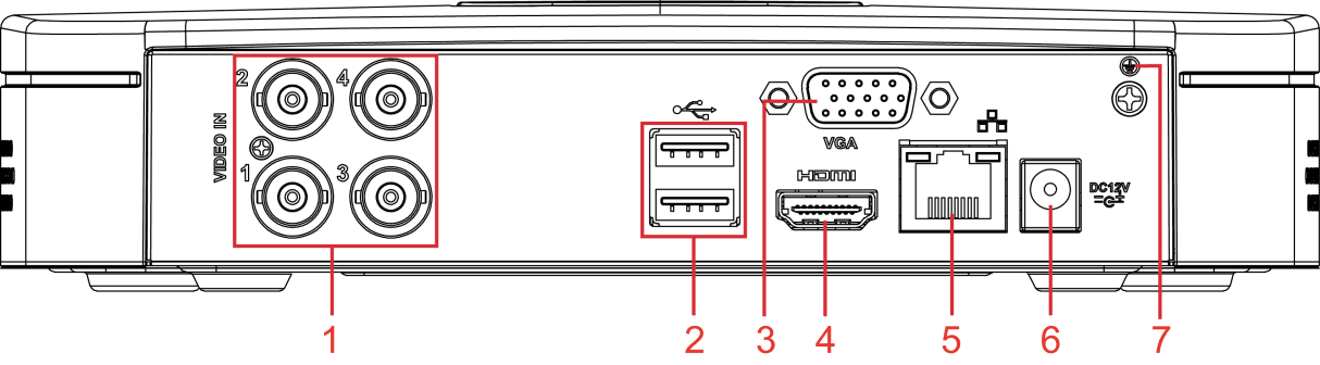
Smart 1U
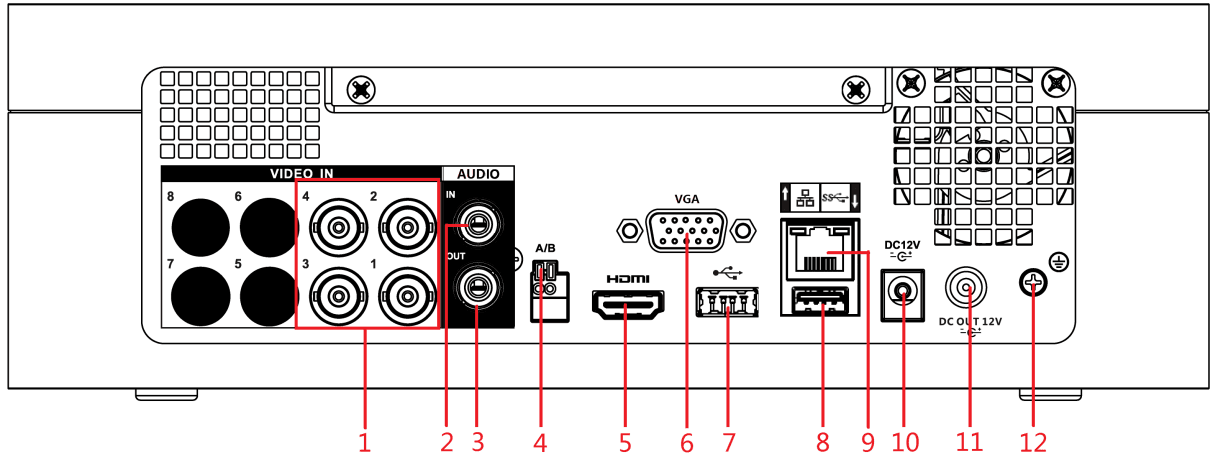
| No. | Port Name | Function |
|---|---|---|
| 1 | Video input port | Connects to analog camera to input video signal. |
| 2 | USB port | Connects to external devices such as USB storage device, keyboard and mouse. |
| 3 | VGA port | Outputs analog video data to the connected display with VGA port. |
| 4 | HDMI port | High definition audio and video signal output port. The port outputs the uncompressed high definition video and multi-channel audio data to the connected display with HDMI port. |
| 5 | Network port | Connects to Ethernet port. |
| 6 | Power input port | Inputs 12V DC power. |
| 7 | Ground terminal. |
E Model
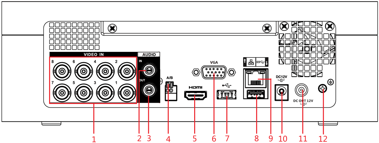
| No. | Port Name | Function |
|---|---|---|
| 1 | Video input port | Connects to analog camera to input video signal. |
| 2 | Audio input port | Receives audio signal output from the devices such as microphone. |
| 3 | Audio output port | Outputs audio signal to the devices such as the sound box. |
| 4 | RS-485 communication port | Connects to the control devices such as speed dome PTZ. RS-485_A port is connected by the cable A and RS-485_B is connected to the cable B. |
| 5 | HDMI port | High definition audio and video signal output port. The port outputs the uncompressed high definition video and multi-channel audio data to the connected display with HDMI port. |
| 6 | VGA port | Outputs analog video data to the connected display with VGA port. |
| 7, 8 | USB port | Connects to external devices such as USB storage device, keyboard and mouse. |
| 9 | Network port | Connects to Ethernet port. |
| 10 | Power input port | Inputs 12V DC power. |
| 11 | Power output port | Outputs 12V DC power. |
| 12 | Ground | Ground terminal. |
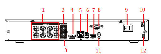
Compact 1U
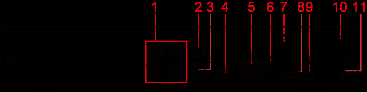
| No. | Port Name | Function |
|---|---|---|
| 1 | Video input port | Connects to analog camera to input video signal. |
| 2 | Audio input port | Receives audio signal output from the devices such as microphone. |
| 3 | Audio output port | Outputs audio signal to the devices such as the sound box. |
| 4 | HDMI port | High definition audio and video signal output port. The port outputs the uncompressed high definition video and multi-channel audio data to the connected display with HDMI port. |
| 5 | Network port | Connects to Ethernet port. |
| 6 | RS-485 communication port | Connects to the control devices such as speed dome PTZ. RS-485_A port is connected by the cable A and RS-485_B is connected to the cable B. |
| 7 | VGA port | Outputs analog video data to the connected display with VGA port. |
| 8 | USB port | Connects to external devices such as USB storage device, keyboard and mouse. |
| 9 | Power input port | Inputs 12V DC power. |
| 10 | Power cable fastener | Use clamp to secure the power cable on the DVR in case there is any loss. |
| 11 | Ground terminal. |
MINI 1U
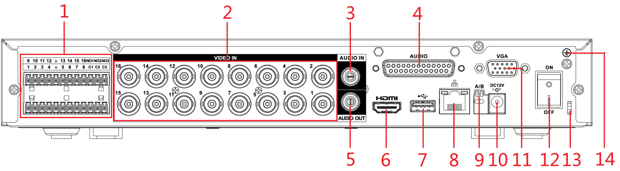
| No. | Port Name | Function |
|---|---|---|
| 1 | Alarm input port 1–16 | Four groups of alarm input ports (Group 1: port 1 to port 4; Group 2: port 5 to port 8; Group 3: port 9 to port 12; Group 4: port 13 to port 16). These ports receive the signal from the external alarm source. There are two types: NO (Normally Open) and NC (Normally Closed). When your alarm input device is using external power, please make sure the alarm input device and the Device have the same ground. |
| 1 | Alarm output port 1–3 (NO1–NO3; C1–C3) | Three groups of alarm output ports (Group 1: port NO1–C1, Group 2: port NO2–C2, Group 3: port NO3–C3). These ports output alarm signal to the alarm device. Please make sure power supply to the external alarm device. NO: Normally open alarm output port. C: Alarm output public end. |
| 1 | Ground. | |
| 2 | Video input port | Connects to analog camera to input video signal. |
| 3 | Audio input port | Receives audio signal output from the devices such as microphone. It corresponds to video input port 1. |
| 4 | DB25 port | Connects to the audio splitter taken from the package to convert to audio input port which receives the audio signal from devices such as microphone. It corresponds to video input ports 2–16. |
| 5 | Audio output port | Outputs audio signal to the devices such as the sound box. |
| 6 | HDMI port | High definition audio and video signal output port. The port outputs the uncompressed high definition video and multi-channel audio data to the connected display with HDMI port. |
| 7 | USB port | Connects to external devices such as USB storage device, keyboard and mouse. |
| 8 | Network port | Connects to Ethernet port. |
| 9 | RS-485 communication port | Connects to the control devices such as speed dome PTZ. RS-485_A port is connected by the cable A and RS-485_B is connected to the cable B. |
| 10 | Power input port | Inputs 12V DC power. |
| 11 | VGA port | Outputs analog video data to the connected display with VGA port. |
| 12 | Power button | Turns on/off the DVR. |
| 13 | Power cable fastener | Use a cable tie to secure the power cable on the DVR to prevent loss. |
| 14 | Ground terminal. |
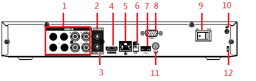
| No. | Port Name | Function |
|---|---|---|
| 1 | Video input port | Connect to general analog camera/PoC camera to input video signal. |
| 2 | Audio input port | Receives the analog audio signal output from the devices such as microphone. |
| 3 | Audio output port | Outputs the analog audio signal to the devices such as the sound box. |
| 4 | HDMI port | High definition audio and video signal output port. It outputs the same video source as VGA. It supports 4K resolution output and supports mouse operation and control. Please note when the HDMI output resolution is 4K, the VGA output stops. |
| 5 | Network port | Connects to Ethernet port. |
| 6 | RS-485 communication port | Connects to the control devices such as speed dome PTZ. RS-485_A port is connected by the cable A and RS-485_B is connected to the cable B. |
| 7 | USB port | Connects to external devices such as USB storage device, keyboard and mouse. |
| 8 | VGA port | Outputs analog video data to the connected display with VGA port. |
| 9 | Network port | Connects to Ethernet port. |
| 10 | Ground terminal. | |
| 11 | Power input port | Inputs 12V DC power. |
| 12 | Power cable fastener | Use clamp to secure the power cable on the DVR in case there is any loss. |
Cooper 1U
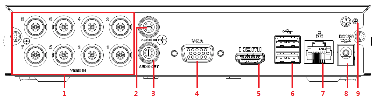
| No. | Port Name | Function |
|---|---|---|
| 1 | Video input port | Connect to analog camera to input video signal. |
| 2 | Audio input port | Receives the analog audio signal output from the devices such as microphone. |
| 3 | Audio output port | Outputs the analog audio signal to the devices such as the sound box. |
| 4 | VGA video output | Outputs analog video signal. It can connect to the monitor to view analog video. |
| 5 | HDMI port | High definition audio and video signal output port. It outputs the same video source as VGA. It supports 4K resolution output and supports mouse operation and control. Please note when the HDMI output resolution is 4K, the VGA output stops. |
| 6 | USB port | Connects to the external devices such as keyboard, mouse, and USB storage device. |
| 7 | Network port | Connects to Ethernet port. |
| 8 | Power input port | Inputs power. |
| 9 | GND | Ground. |
1U
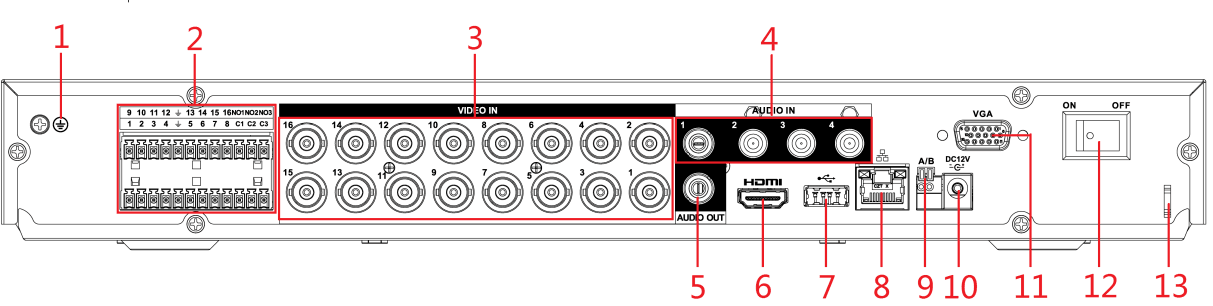
| No. | Port Name | Function |
|---|---|---|
| 1 | Ground terminal. | |
| 2 | Alarm input port 1–16 | Four groups of alarm input ports (Group 1: port 1 to port 4; Group 2: port 5 to port 8; Group 3: port 9 to port 12; Group 4: port 13 to port 16). These ports receive the signal from the external alarm source. There are two types: NO (Normally Open) and NC (Normally Closed). When your alarm input device is using external power, please make sure the alarm input device and the DVR connect to the same ground. |
| 2 | Alarm output port 1–3 (NO1–NO3; C1–C3) | Three groups of alarm output ports. (Group 1: port NO1–C1, Group 2: port NO2–C2, Group 3: port NO3–C3). These ports output alarm signal to the alarm device. Please make sure power supply to the external alarm device. NO: Normally open alarm output port. C: Alarm output public end. |
| 2 | Ground. | |
| 3 | Video input port | Connects to analog camera to input video signal. |
| 4 | Audio input port | Receives audio signal output from the devices such as microphone. |
| 5 | Audio output port | Outputs audio signal to the devices such as the sound box. |
| 6 | HDMI port | High definition audio and video signal output port. The port outputs the uncompressed high definition video and multi-channel audio data to the connected display with HDMI port. |
| 7 | USB port | Connects to the external devices such as keyboard, mouse, and USB storage device. |
| 8 | Network port | Connects to Ethernet port. |
| 9 | RS-485 communication port | Connects to the control devices such as speed dome PTZ. RS-485_A port is connected by the cable A and RS-485_B is connected to the cable B. |
| 10 | Power input port | Inputs 12V DC power. |
| 11 | VGA port | Outputs analog video data to the connected display with VGA port. |
| 12 | Power button | Turns on/off the DVR. |
| 13 | Power cable fastener | Use clamp to secure the power cable on the DVR in case there is any loss. |
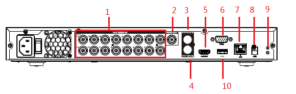
| No. | Port Name | Function |
|---|---|---|
| 1 | Video input port | Connect to general analog camera/PoC camera to input video signal. |
| 2 | Video output port | Connects to video output devices such as TV. |
| 3 | Audio input port | Receives the analog audio signal output from the devices such as microphone. |
| 4 | Audio output port | Outputs the analog audio signal to the devices such as the sound box. |
| 5 | HDMI port | High definition audio and video signal output port. It outputs the same video source as VGA. It supports 4K resolution output and supports mouse operation and control. Please note when the HDMI output resolution is 4K, the VGA output stops. |
| 6 | VGA video output | Outputs analog video signal. It can connect to the monitor to view analog video. |
| 7 | Network port | Connects to Ethernet port. |
| 8 | RS-485 communication port | Connects to the control devices such as speed dome PTZ. RS-485_A port is connected by the cable A and RS-485_B is connected to the cable B. |
| 9 | Ground terminal. | |
| 10 | USB port | Connects to external devices such as USB storage device, keyboard and mouse. |
1.5U
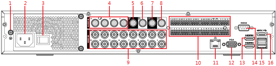
| No. | Port Name | Function |
|---|---|---|
| 1 | Ground terminal. | |
| 2 | Power input port | Inputs power. |
| 3 | Power button | Turns on/off the DVR. |
| 4 | Audio input port | Receives audio signal output from the devices such as microphone. |
| 5 | Audio input port (MIC IN) | Two-way talk input port which receives analog audio signal output from the devices such as microphone and pickup. |
| 6 | Audio output port (MIC OUT) | Two-way talk output port which outputs the analog audio signal to the devices such as the sound box. |
| 7 | Audio output port | Outputs audio signal to the devices such as the sound box. |
| 8 | Video output port | Connects to video output devices such as TV. |
| 9 | Video input port | Connects to analog camera to input video signal. |
| 10 | Alarm input port 1–16 | Four groups of alarm input ports (Group 1: port 1 to port 4; Group 2: port 5 to port 8; Group 3: port 9 to port 12; Group 4: port 13 to port 16). These ports receive the signal from the external alarm source. There are two types: NO (Normally Open) and NC (Normally Closed). When your alarm input device is using external power, please make sure the input device and the DVR connect to the same ground. |
| 10 | Alarm output port 1–5 (NO1–NO5; C1–C5; NC5) | Five groups of alarm output ports (Group 1: port NO1–C1, Group 2: port NO2–C2, Group 3: port NO3–C3, Group 4: port NO4–C4, Group 5: port NO5, C5, NC5). These ports output alarm signal to the alarm device. Please make sure power supply to the external alarm device. NO: Normally open alarm output port. C: Alarm output public end. NC: Normally closed alarm output port. |
| 10 | RS-485 communication port | Connects to the control devices such as speed dome PTZ. RS-485_A port is connected by the cable A and RS-485_B is connected to the cable B. |
| 10 | Four-wire full-duplex RS-485 port (T+, T-, R+, R-) | Four-wire full-duplex 485 port. T+ and T- is the output wire; R+ and R- is the input wire. |
| 10 | Power output control for alarm (CTRL 12V) | Controls the 6th channel power output for alarm. Turns off power output when there is alarm output. Turns on power output when the alarm is cleared. |
| 10 | 12V power output port | Provides power to external devices such as camera and alarm device. Please note the power supply shall be below 1A. |
| 10 | Ground. | |
| 11 | Network port | Connects to Ethernet port. |
| 12 | VGA port | Outputs analog video data to the connected display with VGA port. |
| 13 | HDMI port | High definition audio and video signal output port. The port outputs the uncompressed high definition video and multi-channel audio data to the connected display with HDMI port. Resolution varies depending on different models. |
| 14 | RS-232 debug COM | The port is used for general COM debug to configure IP address or transfer transparent COM data. |
| 15 | USB port | Connects to the external devices such as keyboard, mouse, and USB storage device. |
| 16 | eSATA port | External SATA port which connects to the device with SATA port. Perform the jumper configuration when connecting HDD. |
2U
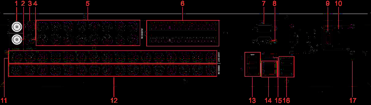
| No. | Port Name | Function |
|---|---|---|
| 1 | Audio output port | Outputs the analog audio signal to the devices such as the sound box. |
| 2 | Video output port | Connect to video output devices such as TV. |
| 3 | Audio input port (MIC IN) | Two-way talk input port which receives the analog audio signal output from the devices such as microphone, pickup. |
| 4 | Audio output port (MIC OUT) | Two-way talk output port which outputs the analog audio signal to the devices such as the sound box. |
| 5 | Audio input port | Receives the analog audio signal output from the devices such as microphone. |
| 6 | Alarm input port 1–16 | Four groups of alarm output ports (Group 1: port 1 to port 4; Group 2: port 5 to port 8; Group 3: port 9 to port 12; Group 4: port 13 to port 16). These ports receive the signal from the external alarm source. There are two types; NO (Normally Open) and NC (Normally Closed). When your alarm input device is using external power, please make sure the device and the NVR have the same ground. |
| 6 | Alarm output port 1–5 (NO1–NO5; C1–C5; NC5) | Five groups of alarm output ports. (Group 1: port NO1–C1, Group 2: port NO2–C2, Group 3: port NO3–C3, Group 4: port NO4–C4, Group 5: port NO5, C5, NC5). These ports output alarm signal to the alarm device. Please make sure power supply to the external alarm device. NO: Normally open alarm output port. C: Alarm output public end. NC: Normally closed alarm output port. |
| 6 | RS-485 communication port | You can connect to the control devices such as speed dome PTZ. RS-485_A port is connected by the cable A and RS-485_B is connected to the cable B. |
| 6 | Four-wire full-duplex RS-485 port (T+, T-, R+, R-) | Four-wire full-duplex 485 port. T+ and T- is the output wire; R+ and R- is the input wire. |
| 6 | Power output control for alarm (CTRL 12V) | Controls the 6th channel power output for alarm. It is to control the on-off alarm relay output. |
| 6 | 12V power output port | Provides power to external devices such as camera and alarm device. Please note the supplying power shall be below 1A. |
| 6 | G | Ground. |
| 7 | RS-232 debug COM | It is for general COM debug to configure IP address or transfer transparent COM data. |
| 8 | VGA video output | Outputs analog video signal. It can connect to the monitor to view analog video. |
| 9 | Power button | Turns on/off the Device. |
| 10 | Power input port | Inputs power. |
| 11 | Loop out | Outputs the video signal of the corresponding video input port. |
| 12 | Video input port | Connect to analog camera to input video signal. |
| 13 | Network port | Connects to Ethernet port. |
| 14 | USB port | Connects to the external devices such as keyboard, mouse, and USB storage device. |
| 15 | eSATA port | External SATA port which connects to the device with SATA port. Perform the jumper configuration when connecting HDD. |
| 16 | HDMI port | High definition audio and video signal output port. It outputs the same video source as VGA. It supports 4K resolution output and supports mouse operation and control. Please note when the HDMI output resolution is 4K, the VGA output stops. Resolution varies depending on different models. |
| 17 | GND | Ground. |
Remote Control Operations
The remote control is not our standard accessory and might not be included in the accessory bag. It is supplied dependent on the model you purchased.
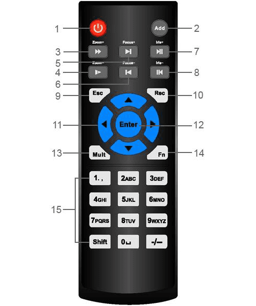
| No. | Name | Function |
|---|---|---|
| 1 | Power button | Press this button to boot up or shut down the device. |
| 2 | Address | Press this button to input device serial number, so that you can control the Device. |
| 3 | Forward | Multi-step forward speed and normal speed playback. |
| 4 | Slow motion | Multi-step slow motion speed or normal playback. |
| 5 | Next record | In playback state, press this button to play back the next video. |
| 6 | Previous record | In playback state, press this button to play back the previous video. |
| 7 | Play/Pause | In normal playback state, press this button to pause playback. In pause state, press this button to resume to normal playback. In live view window interface, press this button to enter video search menu. |
| 8 | Reverse/pause | In the reverse playback state, press this button to pause reverse playback. In the reverse playback pause state, press this button to resume to playback reversing state. |
| 9 | Esc. | Go back to previous menu or cancel current operation (close front interface or control). |
| 10 | Record | Start or stop record manually. In record interface, use the direction buttons to select the channel that you want to record. Press this button for at least 1.5 seconds, and the manual record interface will be displayed. |
| 11 | Direction keys | Switch between current activated controls by going left or right. In playback state, the keys control the playback progress bar. Aux function (such as operating the PTZ menu). |
| 12 | Enter/menu key | Confirms an operation. Go to the OK button. Go to the menu. |
| 13 | Multiple-window switch | Switch between multiple-window and one-window. |
| 14 | Fn | In single-channel monitoring mode, press this button to display the PTZ control and color setting functions. Switch the PTZ control menu in PTZ control interface. In motion detection interface, press this button with direction keys to complete setup. In text mode, press and hold this button to delete the last character. To use the clearing function: Long press this button for 1.5 seconds. In HDD menu, switch HDD recording time and other information as indicated in the pop-up message. |
| 15 | Alphanumeric keys | Input password, numbers. Switch channel. Press Shift to switch the input method. |
Mouse Operations
The operations are based on the considerations for right-handed users.
| Operation | Function |
|---|---|
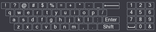
| Click left mouse button | Password input dialogue box pops up if you have not logged in yet. In live view window interface, you can go to the main menu. When you have selected one menu item, click it to view menu content. Implement the control operation. Modify check box or motion detection status. Click combo box to pop up drop-down list. In text box, click the corresponding button on the panel to enter a numeral or English character (small/capitalized). In English input mode: Click the backspace icon to enter a backspace and click the delete icon to delete the previous character. In numeral input mode: Click the clear icon to clear and click the delete icon to delete the previous character. |
| Double-click left mouse button | Implement special control operations such as double-click one item in the file list to play back the video. In multiple-window mode, double-click one channel to view in full-window. Double-click current video again to go back to previous multiple-window mode. |
| Right-click | Right-click in live view window interface, the shortcut menu is displayed. For different series product, the shortcut menu may vary. Exit current menu without saving the modification. |
| Click scroll wheel button | In numeral input box: Increase or decrease numeral value. Switch the items in the combo box. Page up or page down. |
| Point to select and move | Select current control and move it. |
| Dragging a selection box with left mouse button | Select motion detection zone. Select privacy mask zone. |
The on-screen soft keyboard panel used for text and numeral input is shown below.
Getting Started
How to check the components, install the HDD for each chassis form factor (Smart 1U, E Model, MINI 1U and Compact 1U, Cooper 1U, 1U, 1.5U, and 2U), and mount the DVR into a rack.
Connecting Basics
Typical connection diagrams and port connections for the Sapphire Series CVI DVR, covering video and audio input/output, alarm input/output, relay parameters, and the RS-485 port.