 LTS Connect ヘルプセンター
Alarm Events Settings
Configure alarm information, alarm input and output, video detection, and system event alarms on the Sapphire Series CVI DVR.
Alarm Information
You can search, view and back up the alarm information.
Open ALARM INFO
Select Main Menu > ALARM > ALARM INFO.
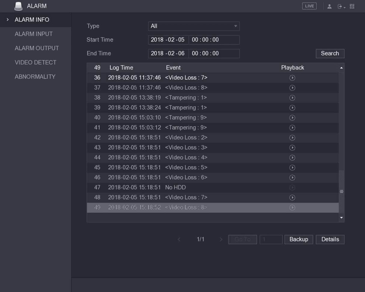
The ALARM INFO interface is displayed. See Figure 5-115.
Set the search conditions
In the Type list, select the event type; In the Start Time box and End Time box, enter the specific time.
Back up the results
Click Backup to back up the search results into the external storage device.
- Click
 to play the recorded video of alarm event.
 - Select an event and click Details to view the detailed information of the event.
Alarm Input Settings
Connect the alarm input and output ports by referring to "4.3 Connecting to Alarm Input and Output." You can configure the alarm settings for each channel individually or apply the settings to all channels and then save the settings.
Configuring Local Alarms
You can connect the alarm device to the alarm input port of the Device. When the alarm is activated on the alarm device, the alarm information will be uploaded to the Device, and then the Device outputs the local alarms in the way that you configure in this section.
Open the Local interface
Select Main Menu > ALARM > ALARM INPUT > Local.
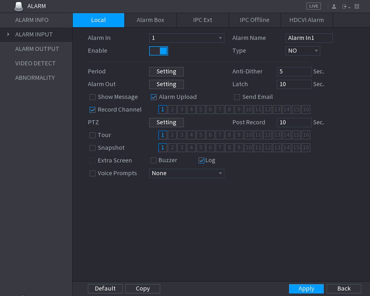
The Local interface is displayed. See Figure 5-116.
Configure the local alarm settings
Configure the settings for the local alarms. See Table 5-35.
| Parameter | Description |
|---|---|
| Alarm In | Select the channel number. |
| Alarm Name | Enter the customized alarm name. |
| Enable | Enable or disable the local alarm function. |
| Type | In the Type list, select NO or select NC as the voltage output type. |
| Period | Click Setting to display setting interface. Define a period during which the motion detection is active. For details, see "Setting Motion Detection Period" section in "5.10.4.1 Configuring Motion Detect Settings." |
| Anti-Dither | Configure the time period from end of event detection to the stop of alarm. |
| Alarm Out | Click Setting to display setting interface. General Alarm: Enable alarm activation through the alarm devices connected to the selected output port. External Alarm: Enable alarm activation through the connected alarm box. Wireless Siren: Enable alarm activation through devices connected by USB gateway or camera gateway. |
| Latch | Set a length of time for the Device to delay turning off alarm after the external alarm is cancelled. The value ranges from 0 seconds to 300 seconds, and the default value is 10 seconds. |
| Show Message | Select the Show Message check box to enable a pop-up message in your local host PC. |
| Alarm Upload | Select the Alarm Upload check box to enable the system to upload the alarm signal to the network (including alarm center) when an alarm event occurs. |
| Send Email | Select the Send Email check box to enable the system to send an email notification when an alarm event occurs. To use this function, make sure the email function is enabled in Main Menu > NETWORK > EMAIL. |
| Record Channel | Select the channel(s) that you want to record. The selected channel(s) starts recording after an alarm event occurs. The recording for local alarm recording and auto recording must be enabled. For details, see "5.1.4.9 Configuring Recorded Video Storage Schedule" and "5.9.1 Enabling Record Control." |
| PTZ | Click Setting to display the PTZ interface. Enable PTZ linkage actions, such as selecting the preset that you want to be called when an alarm event occurs. |
| Post Record | Set a length of time for the Device to delay turning off recording after the alarm is cancelled. The value ranges from 10 seconds to 300 seconds, and the default value is 10 seconds. |
| Tour | Select the Tour check box to enable a tour of the selected channels. |
| Snapshot | Select the Snapshot check box to take a snapshot of the selected channel. To use this function, select Main Menu > CAMERA > ENCODE > Snapshot, in the Mode list, select Event. |
| Extra Screen | Select the check box to enable the function. When an alarm event occurs, the extra screen outputs the settings configured in Main Menu > DISPLAY > TOUR > Extra Screen. Not all models support this function. To use this function, extra screen shall be enabled. |
| Video Matrix | Select the check box to enable the function. When an alarm event occurs, the video output port outputs the settings configured in Main Menu > DISPLAY > TOUR. Not all models support this function. |
| Buzzer | Select the check box to activate a buzzer noise at the Device. |
| Log | Select the check box to enable the Device to record a local alarm log. |
| Voice Prompts | Select to enable audio broadcast/voice prompts in response to a local alarm event. |
Apply
Click Apply to complete the settings.
- Click Default to restore the default setting.
- Click Copy, in the Copy dialog box, select the additional channel(s) that you want to copy the local alarm settings to, and then click Apply.
Configuring Alarms from Alarm Box
You can connect the alarm box to the RS-485 port of the Device. When the alarm is detected by the alarm box, the alarm information will be uploaded to the Device, and then the Device outputs the alarms in the way that you configure in this section.
Open the Alarm Box interface
Select Main Menu > ALARM > ALARM INPUT > Alarm Box.
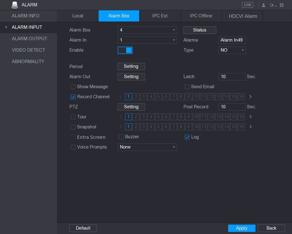
The Alarm Box interface is displayed. See Figure 5-117.
Select the alarm box
In the Alarm Box list, select the alarm box number corresponding to the address number configured by the DIP switch on the Alarm Box.
Select the alarm input port
In the Alarm In list, select the alarm input port on the Alarm Box.
Configure other parameters
Configure the settings for other parameters of the Alarm Box. For details, see Table 5-35.
Configuring Alarms from External IP Cameras
Open the IPC Ext interface
Select Main Menu > ALARM > ALARM INPUT > IPC Ext.
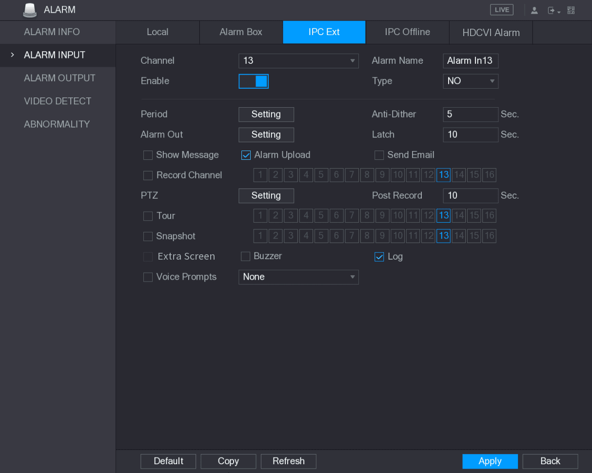
The IPC Ext interface is displayed. See Figure 5-118.
Configure the alarm input settings
Configure the alarm input settings from the external IPC. For details, see Table 5-35.
Apply
Click Apply to complete the settings.
- Click Default to restore the default setting.
- Click Copy to copy the settings to other channels.
- Click Refresh to refresh configured settings.
Configuring Alarms for IP Camera Offline
You can configure the alarm settings for the situation when the IP camera is offline.
Open the IPC Offline interface
Select Main Menu > ALARM > ALARM INPUT > IPC Offline.
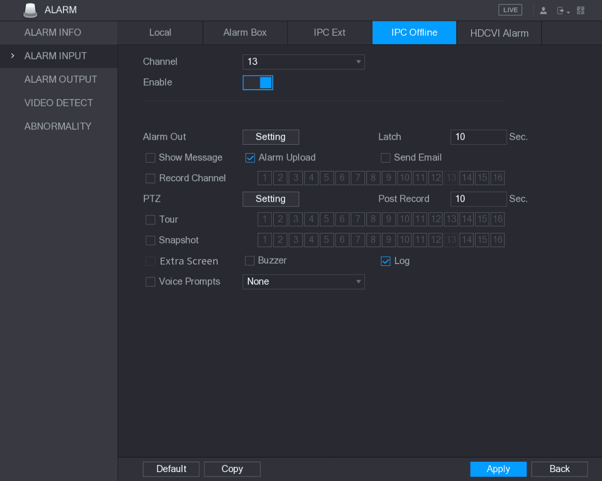
The IPC Offline interface is displayed. See Figure 5-119.
Configure the alarm input settings
Configure the alarm input settings from the offline IPC. For details, see Table 5-35.
Apply
Click Apply to complete the settings.
- Click Default to restore the default setting.
- Click Copy to copy the settings to other channels.
Configuring Alarms from HDCVI Devices
Open the HDCVI Alarm interface
Select Main Menu > ALARM > ALARM INPUT > HDCVI Alarm.
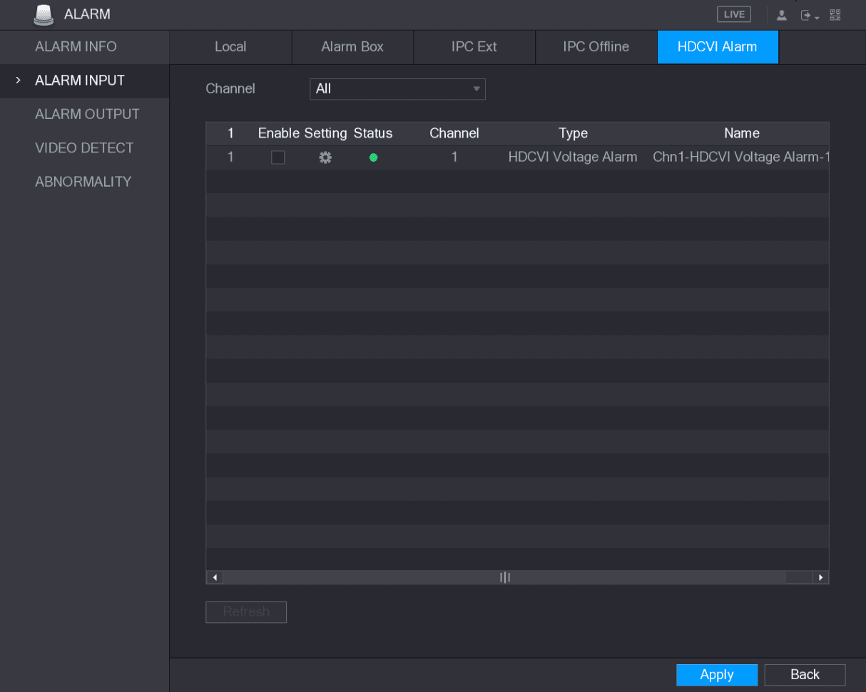
The HDCVI Alarm interface is displayed. See Figure 5-120.
Select a channel
In the Channel list, select a channel or all.
 .
.
Configure other parameters
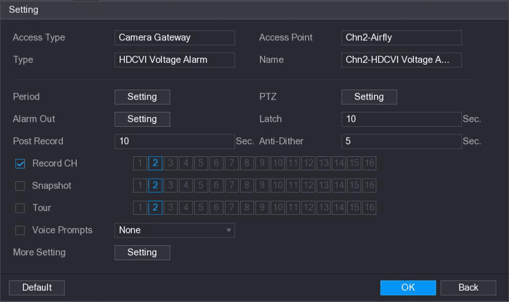
Configure the settings for other parameters of the Alarm Box. For details, see Table 5-35.
Save
Click OK to save the settings.
Apply
Click Apply to complete the settings.
Alarm Output Settings
Configuring Alarm Output
When the Device activates alarms, the connected alarm device generates alarms in the way that you can configure in this section. You can connect to the output port of the Device or connect wirelessly.
- Auto: When an alarm event is triggered on the Device, the connected alarm device generates alarms.
- Manual: The alarm device is forced to keep generating alarms.
- Stop: The alarm output function is not enabled.
Open the ALARM OUTPUT interface
Select Main Menu > ALARM > ALARM OUTPUT > ALARM Out.
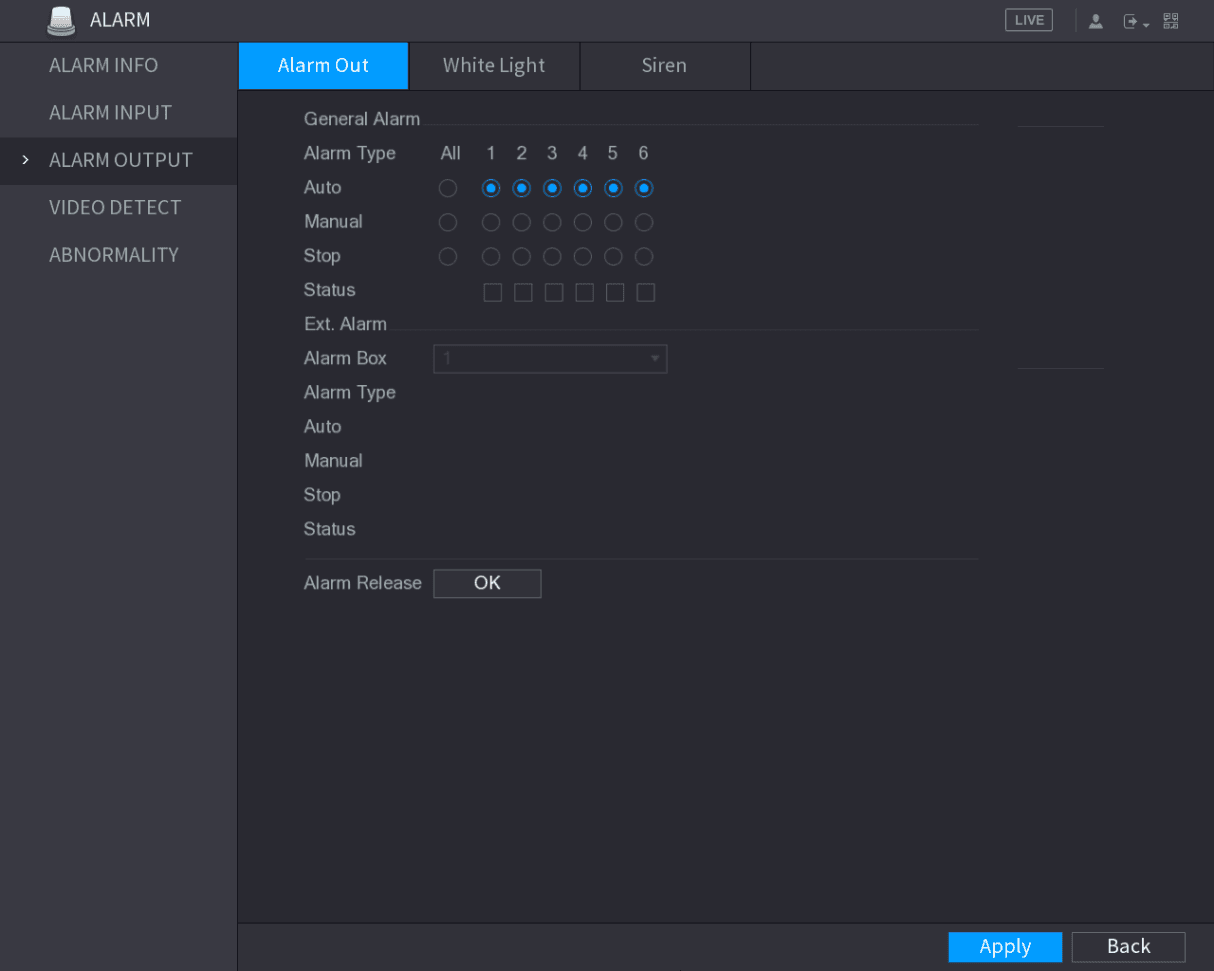
The ALARM OUTPUT interface is displayed. See Figure 5-122.
Configure the alarm output
Configure the settings for the alarm output. For details, see Table 5-36.
| Parameter | Description | |
|---|---|---|
| General Alarm | Alarm Type | Select alarm type for each alarm output port. |
| General Alarm | Status | Indicates the status of each alarm output port. |
| Ext. Alarm | Alarm Box | Select the alarm box number corresponding to the address number configured by the DIP switch on the Alarm Box. |
| Ext. Alarm | Alarm Type | Select the alarm type for each alarm output ports. |
| Ext. Alarm | Status | Indicates the status of each alarm output port. |
| Alarm Release | Click OK to clear all alarm output status. |
Apply
Click Apply to save the settings.
Configuring White Light
When the motion detection alarm is activated, the system links the camera to generate white light alarm.
To use this function, connect at least one white light camera to your Device.
Open the White Light interface
Select Main Menu > ALARM > ALARM OUTPUT > White Light.
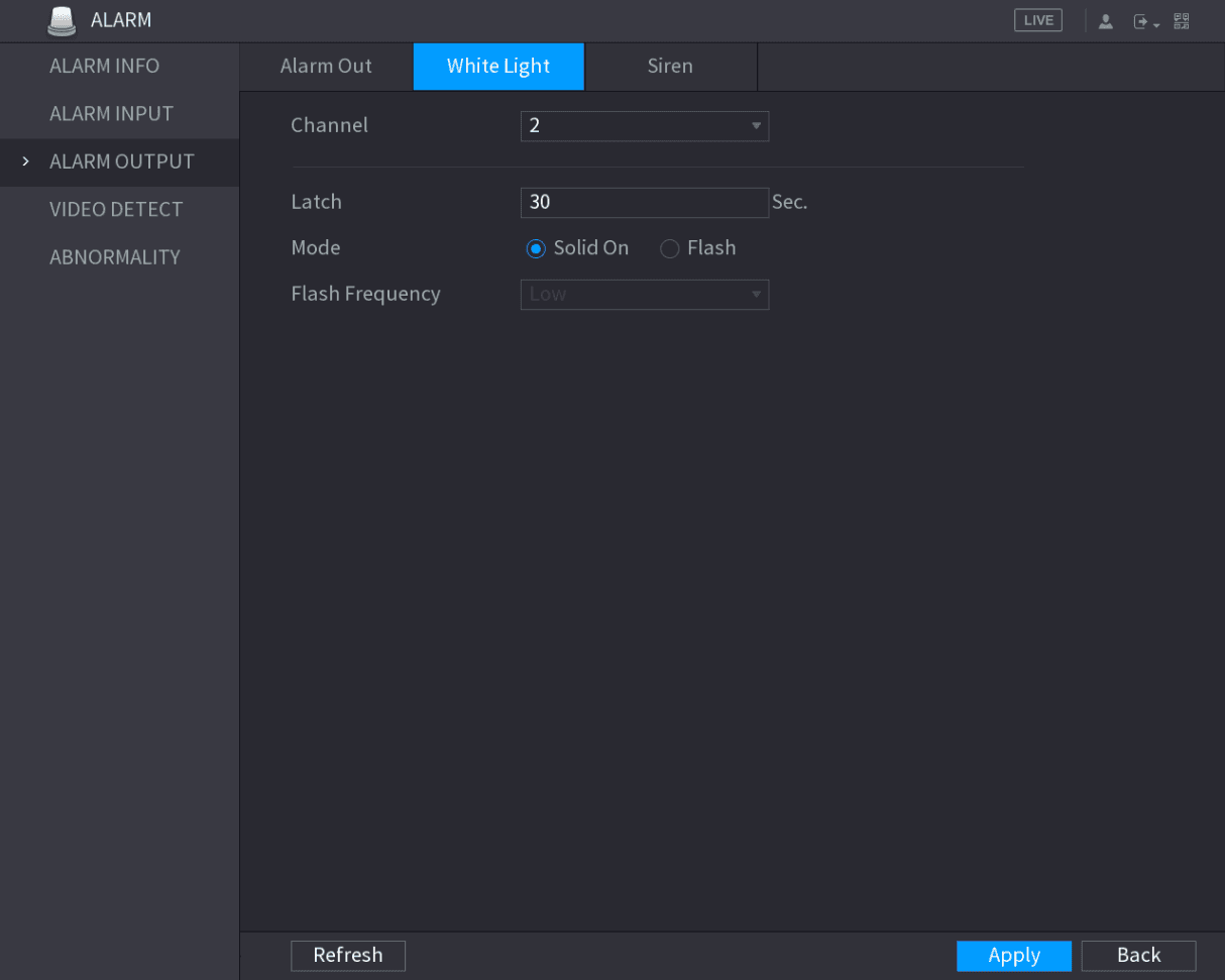
The White Light interface is displayed. See Figure 5-123.
Configure the white light parameters
Configure the settings for the white light parameters. See Table 5-37.
| Parameter | Description |
|---|---|
| Channel | In the Channel list, select a channel that is connected to a white light camera. |
| Latch | Set a length of time for the Device to delay turning off alarm after the alarm is cancelled. The value ranges from 5 seconds to 30 seconds, and the default value is 5 seconds. |
| Mode | Set the alarm mode of white light to be Solid on or Flash. |
| Flash Frequency | When setting the alarm mode of white light to be Flash, you can select the flash frequency from Low, Middle, and High. |
Apply
Click Apply to complete the settings.
Configuring Siren
When the motion detection alarm is activated, the system links the camera to generate sound alarm.
To use this function, connect at least one camera that supports audio function.
Open the Siren interface
Select Main Menu > ALARM > ALARM OUTPUT > Siren.
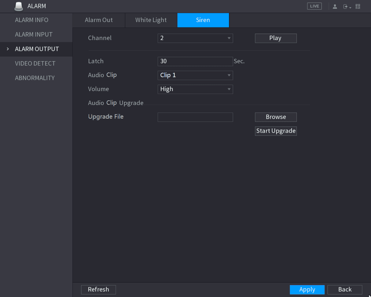
The Siren interface is displayed. See Figure 5-124.
Configure the siren parameters
Configure the settings for the siren parameters. See Table 5-38.
| Parameter | Description |
|---|---|
| Channel | In the Channel list, select a channel that is connected to a camera that supports audio function. |
| Play | Click Play to manually trigger the IP camera to play audio file. |
| Latch | Set a length of time for the Device to delay turning off alarm after the alarm is cancelled. The value ranges from 5 seconds to 30 seconds, and the default value is 5 seconds. |
| Audio Clip | Select the audio clip for the siren sound. The default setting is Clip 1. |
| Volume | Select the volume for the audio clip. You can select the flash frequency from Low, Middle, and High. |
| Update File | Import the upgrade audio file (.bin) to upgrade the alarm audio file of the camera. For details, see "Upgrade Audio File of Camera." |
Apply
Click Apply to complete the settings.
Upgrade Audio File of Camera
This function is supported only on the local interface.
Plug in a storage device
Prepare a USB device or other external storage device and plug it into the Device.
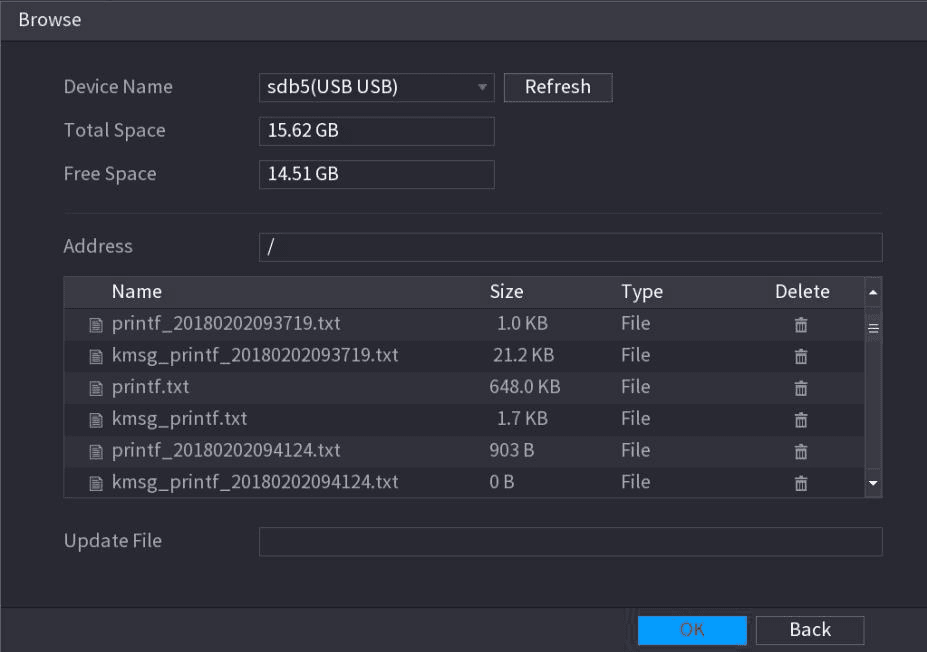
Select the audio file
Select the upgrade audio file (.bin).
Return to the Siren interface
Click OK to return to the Siren interface.
Start the upgrade
Click Start Upgrade to upgrade the alarm audio file of the camera.
Video Detection
Video detection adopts computer vision and image processing technology. The technology analyzes the video images to detect the obvious changes such as moving objects and blurriness. The system activates alarms when such changes are detected.
Configuring Motion Detect Settings
When the moving object appears and moves fast enough to reach the preset sensitivity value, the system activates the alarm.
Open the Motion Detect interface
Select Main Menu > ALARM > VIDIEO DETECT > Motion Detect.
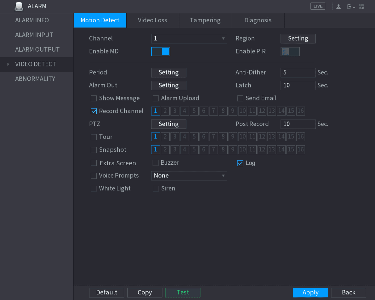
The Motion Detect interface is displayed. See Figure 5-126.
Configure the motion detection parameters
Configure the settings for the motion detection parameters. See Table 5-39.
| Parameter | Description |
|---|---|
| Channel | In the Channel list, select a channel to set the motion detection. |
| Region | Click Setting to define the motion detection region. |
| Enable MD | Enable or disable the motion detection function. |
| Enable PIR | PIR function helps enhancing the accuracy and validity of motion detect. It can filter the meaningless alarms that are activated by the objects such as falling leaves, flies. The detection range by PIR is smaller than the field angle. PIR function is enabled by default if it is supported by the cameras. Enabling PIR function will get the motion detect to be enabled automatically to generate motion detection alarms; if the PIR function is not enabled, the motion detect just has the general effect. Only when the channel type is CVI, the PIR function can be enabled. If the camera does not support PIR function, it will be unusable. If the Device does not support PIR function, it will not be displayed on the interface. |
| Period | Define a period during which the motion detection is active. |
| Anti-Dither | Configure the time period from end of event detection to the stop of alarm. |
| Alarm Out | Click Setting to display setting interface. General Alarm: Enable alarm activation through the alarm devices connected to the selected output port. External Alarm: Enable alarm activation through the connected alarm box. Wireless Siren: Enable alarm activation through devices connected by USB gateway or camera gateway. |
| Latch | Set a length of time for the Device to delay turning off alarm after the external alarm is cancelled. The value ranges from 0 seconds to 300 seconds, and the default value is 10 seconds. If you enter 0, there will be no delay. |
| Show Message | Select the Show Message check box to enable a pop-up message in your local host PC. |
| Alarm Upload | Select the Alarm Upload check box to enable the system to upload the alarm signal to the network (including alarm center) when an alarm event occurs. |
| Send Email | Select the Send Email check box to enable the system to send an email notification when an alarm event occurs. To use this function, make sure the email function is enabled in Main Menu > NETWORK > EMAIL. |
| Record Channel | Select the channel(s) that you want to record. The selected channel(s) starts recording after an alarm event occurs. The recording for motion detection and auto recording function must be enabled. For details, see "5.1.4.9 Configuring Recorded Video Storage Schedule" and "5.9.1 Enabling Record Control." |
| PTZ | Click Setting to display the PTZ interface. Enable PTZ linkage actions, such as selecting the preset that you want to be called when an alarm event occurs. Motion Detect can only activate PTZ preset. |
| Post Record | Set a length of time for the Device to delay turning off recording after the alarm is cancelled. The value ranges from 10 seconds to 300 seconds, and the default value is 10 seconds. |
| Tour | Select the Tour check box to enable a tour of the selected channels. |
| Snapshot | Select the Snapshot check box to take a snapshot of the selected channel. To use this function, select Main Menu > CAMERA > ENCODE > Snapshot, in the Mode list, select Event. |
| Extra Screen | Select the check box to enable the function. When an alarm event occurs, the extra screen outputs the settings configured in Main Menu > DISPLAY > TOUR > Extra Screen. Not all models support this function. To use this function, extra screen shall be enabled. |
| Video Matrix | Select the check box to enable the function. When an alarm event occurs, the video output port outputs the settings configured in Main Menu > DISPLAY > TOUR. Not all models support this function. |
| Buzzer | Select the check box to activate a buzzer noise at the Device. |
| Log | Select the check box to enable the Device to record a local alarm log. |
| Voice Prompts | Select to enable audio broadcast/voice prompts in response to a motion detection event. |
| White Light | Select the check box to enable the white light alarm of the camera. |
| Siren | Select the check box to enable the sound alarm of the camera. |
Apply
Click Apply to save the settings.
- Click Default to restore the default setting.
- Click Copy, in the Copy dialog box, select the additional channel(s) that you want to copy the motion detection settings to, and then click Apply.
- Click Test to test the settings.
Setting the Motion Detection Region
Display the setting interface
Point to the middle top of the interface.
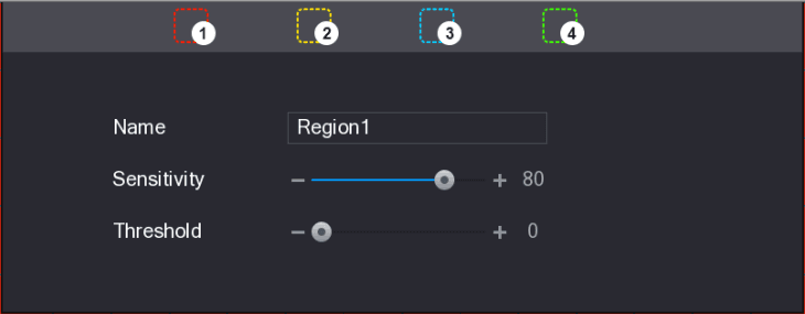
The setting interface is displayed. See Figure 5-127.
Configure the regions
Configure the regions settings. You can configure totally four regions.
- Select one region, for example, click the first region selector.
- Drag on the screen to select the region that you want to detect. The selected area shows the color that represents the region.
- Configure the parameters.
| Parameter | Description |
|---|---|
| Name | Enter a name for the region. |
| Sensitivity | Every region of every channel has an individual sensitivity value. The bigger the value is, the easier the alarms can be activated. |
| Threshold | Adjust the threshold for motion detect. Every region of every channel has an individual threshold. |
When anyone of the four regions activates motion detect alarm, the channel where this region belongs to will activate motion detect alarm.
Exit the region setting interface
Right-click on the screen to exit the region setting interface.
Apply
On the Motion Detect interface, click Apply to complete the settings.
Setting Motion Detection Period
The system only activates the alarm in the defined period.
Open the Setting interface
Next to Period, click Setting.
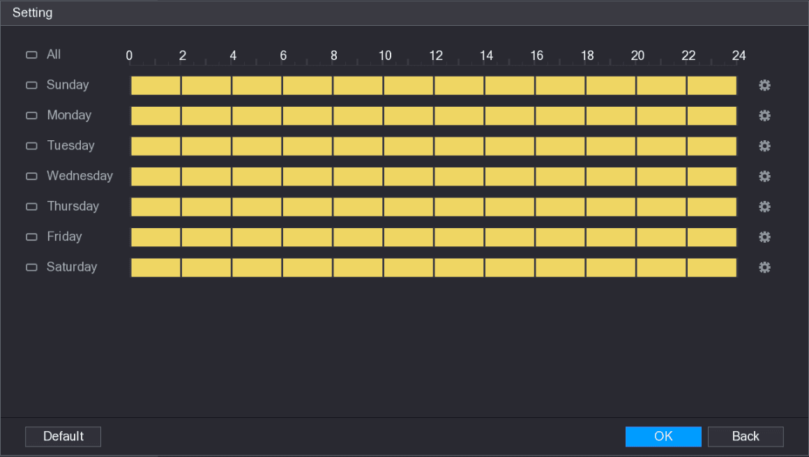
The Setting interface is displayed. See Figure 5-129.
Define the motion detection period
Define the motion detection period. By default, it is active all the time.
Define the period by drawing.
- Define for a specified day of a week: On the timeline, click the half-hour blocks to select the active period.
- Define for several days of a week: Click the lock icon before each day, the icon switches to the linked icon. On the timeline of any selected day, click the half-hour blocks to select the active periods, all the days with the linked icon will take the same settings.
- Define for all days of a week: Click All, all lock icons switch to the linked icon. On the timeline of any day, click the half-hour blocks to select the active periods, all the days will take the same settings.
Define the period by editing. Take Sunday as an example.
-
Click the setting icon.
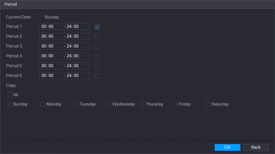
The Period interface is displayed. See Figure 5-130.
-
Enter the time frame for the period, and then select the check box to enable the settings.
- There are six periods for you to set for each day.
- Under Copy, select All to apply the settings to all the days of a week, or select specific day(s) that you want to apply the settings to.
-
Click OK to save the settings.
Apply
On the Motion Detect interface, click Apply to complete the settings.
Configuring Video Loss Settings
When the video loss occurs, the system activates the alarm.
Open the Video Loss interface
Select Main Menu > ALARM > VIDIEO DETECT > Video Loss.
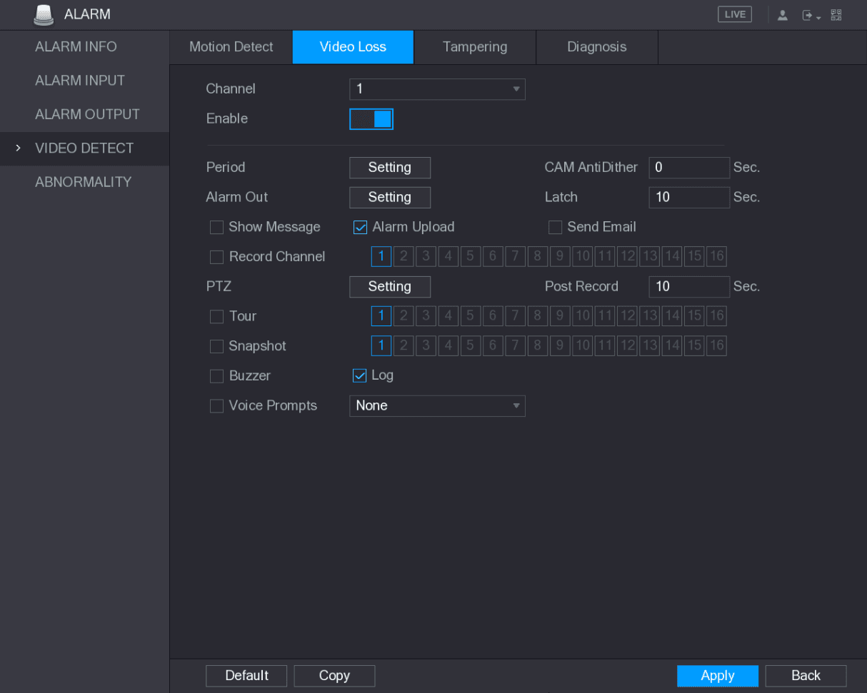
The Video Loss interface is displayed. See Figure 5-131.
Configure the video loss detection settings
To configure the settings for the video loss detection parameters, see "5.10.4.1 Configuring Motion Detect Settings."
For PTZ activation, different from motion detection, the video loss detection can activate PTZ preset, tour, and pattern.
Apply
Click Apply to complete the settings.
- Click Default to restore the default setting.
- Click Copy, in the Copy dialog box, select the additional channel(s) that you want to copy the motion detection settings to, and then click Apply.
Configuring Tampering Settings
When the camera lens is covered, or the video is displayed in a single color because of the causes such as sunlight status, the monitoring cannot be continued normally. To avoid such situations, you can configure the tampering alarm settings.
Open the Tampering interface
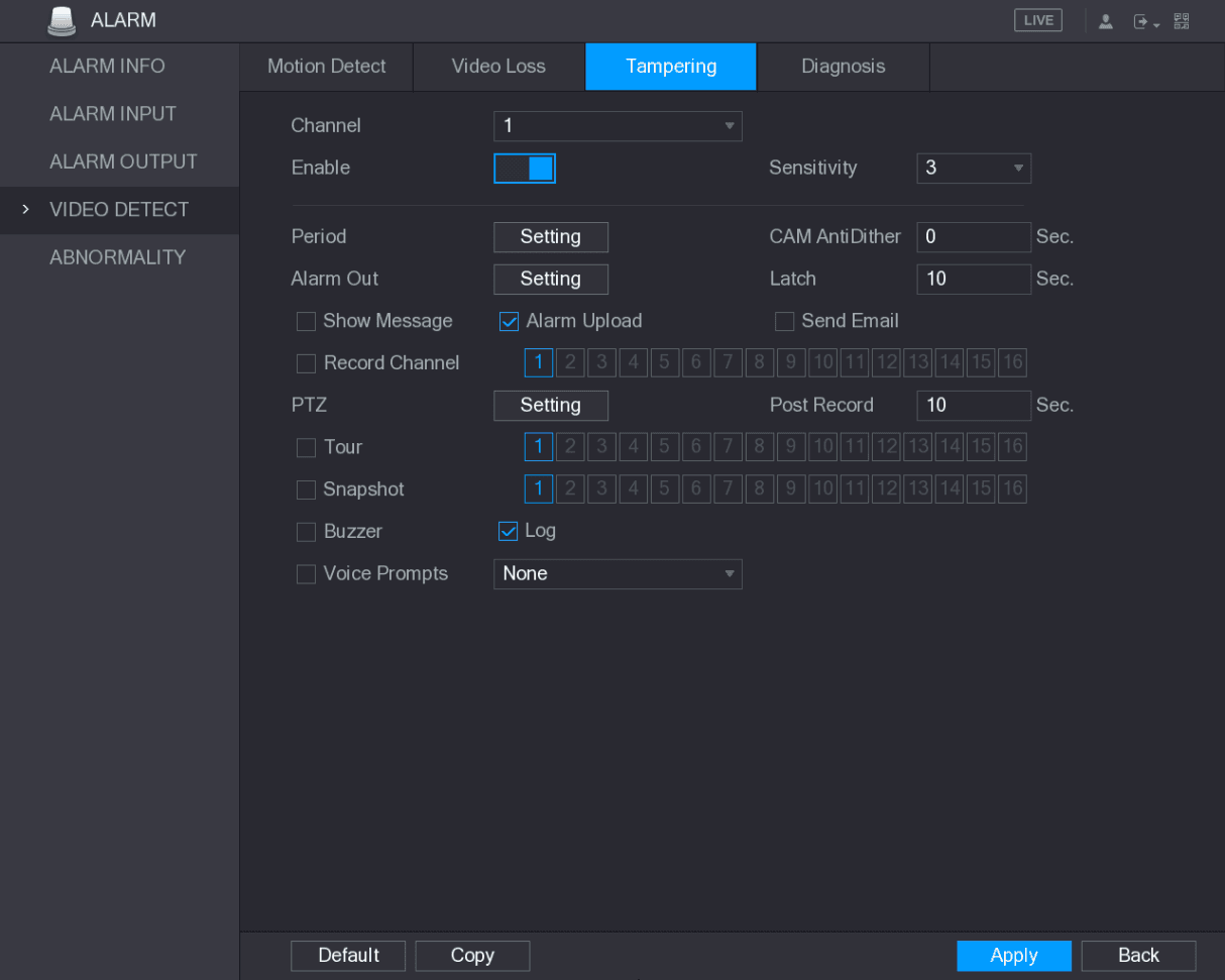
Select Main Menu > ALARM > VIDIEO DETECT > Tampering.
The Tampering interface is displayed. See Figure 5-132.
Configure the tampering detection settings
To configure the settings for the tampering detection parameters, see "5.10.4.1 Configuring Motion Detect Settings."
For PTZ activation, different from motion detection, the video loss detection can activate PTZ preset, tour, and pattern.
Apply
Click Apply to complete the settings.
- Click Default to restore the default setting.
- Click Copy, in the Copy dialog box, select the additional channel(s) that you want to copy the motion detection settings to, and then click Apply.
Configuring Diagnosis Settings
This function can be used only when it is supported by the camera.
When the video appear the conditions such as blurry, overexposed, or the color changes, the system activates the alarm.
Open the Diagnosis interface
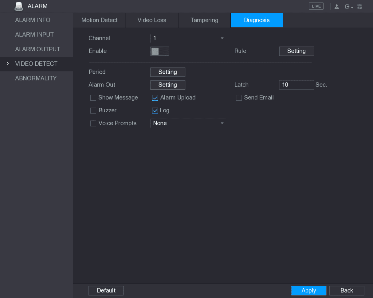
Select Main Menu > ALARM > VIDIEO DETECT > Diagnosis.
The Diagnosis interface is displayed. See Figure 5-133.
Configure the diagnosis settings
To configure the settings for the diagnosis parameters, see "5.10.4.1 Configuring Motion Detect Settings."
Setting the Types for Diagnosing Targets
Open the Diagnosis rule interface
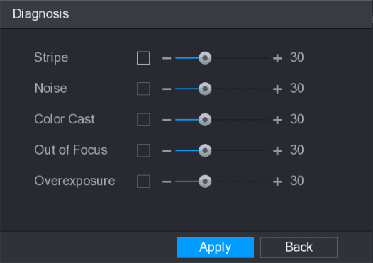
Next to Rule, click Setting.
The Diagnosis interface is displayed. See Figure 5-134.
Select the diagnosing items
Select the items that you want to diagnose and set the threshold (30 by default). See Table 5-40.
| Parameter | Description |
|---|---|
| Stripe | A horizontal, vertical or diagonal stripe that might appear in the video because of device aging or electronic interruption. Such stripe brings visual interruption. |
| Noise | Video noises such as blurriness or quality reduction that is caused by optical distortion or device problem during camera shooting. |
| Color Cast | Variances in the normal proportions of RGB colors. |
| Out of Focus | Blurry video is caused during camera shooting, transferring and processing. Such condition is a common image quality reduction problem and defined as out of focus. |
| Overexposure | The video brightness refers to the intensity of image pixel. The range is between 0 (the darkest black) and 255 (the brightest white). If the brightness exceeds the threshold, the image is over exposed. |
| Threshold | The range is from 1 through 100. If the value after diagnosing is higher than what you set, the system activates the alarm to the corresponding diagnosing types such as stripe. |
Apply the rule settings
Click Apply to save the settings.
The system returns to the Diagnosis interface.
System Events
You can configure the alarm output for three types of system event (HDD, Network, and User). When there is an abnormal system event occurs, the system activates alarms in the way that you configure in this section.
Configuring HDD Event Settings
Open the HDD interface
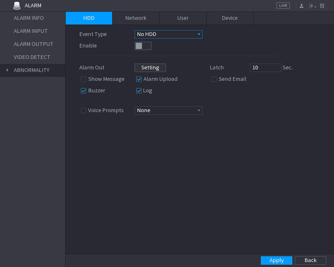
Select Main Menu > ALARM > ABNORMITY > HDD.
The HDD interface is displayed. See Figure 5-135.
Configure the HDD event
Configure the settings for the HDD event. See Table 5-41.
| Parameter | Description |
|---|---|
| Event Type | In the Event Type list, select No HDD, HDD Error, or HDD No Space as the event type. |
| Enable | Enable or disable the HDD event detection function. |
| Alarm Out | Click Setting to display setting interface. General Alarm: Enable alarm activation through the alarm devices connected to the selected output port. External Alarm: Enable alarm activation through the connected alarm box. Wireless Siren: Enable alarm activation through devices connected by USB gateway or camera gateway. |
| Latch | Set a length of time for the Device to delay turning off alarm after the external alarm is cancelled. The value ranges from 10 seconds to 300 seconds, and the default value is 10 seconds. |
| Show Message | Select the Show Message check box to enable a pop-up message in your local host PC. |
| Alarm Upload | Select the Alarm Upload check box to enable the system to upload the alarm signal to the network (including alarm center) when an alarm event occurs. |
| Send Email | Select the Send Email check box to enable the system to send an email notification when an alarm event occurs. To use this function, make sure the email function is enabled in Main Menu > NETWORK > EMAIL. |
| Buzzer | Select the check box to activate a buzzer noise at the Device. |
| Log | Select the check box to enable the Device to record a local alarm log. |
| Voice Prompts | Select to enable audio broadcast/voice prompts in response to a HDD alarm event. |
Apply
Click Apply to complete the settings.
Configuring Network Event Settings
Open the Network interface
Select Main Menu > ALARM > ABNORMITY > Network.
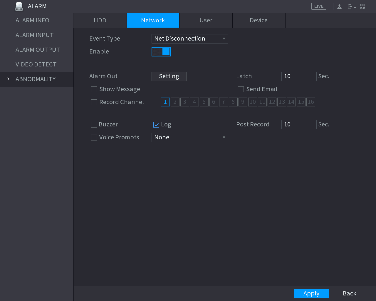
The Network interface is displayed. See Figure 5-136.
Configure the Network event
Configure the settings for the Network event. See Table 5-42.
| Parameter | Description |
|---|---|
| Event Type | In the Event Type list, select Net Disconnection, IP Conflicted, or MAC Conflicted as the event type. |
| Enable | Enable or disable the Network event detection function. |
| Alarm Out | Click Setting to display setting interface. General Alarm: Enable alarm activation through the alarm devices connected to the selected output port. External Alarm: Enable alarm activation through the connected alarm box. Wireless Siren: Enable alarm activation through devices connected by USB gateway or camera gateway. |
| Latch | Set a length of time for the Device to delay turning off alarm after the external alarm is cancelled. The value ranges from 10 seconds to 300 seconds, and the default value is 10 seconds. |
| Show Message | Select the Show Message check box to enable a pop-up message in your local host PC. |
| Send Email | Select the Send Email check box to enable the system to send an email notification when an alarm event occurs. To use this function, make sure the email function is enabled in Main Menu > NETWORK > EMAIL. |
| Buzzer | Select the check box to activate a buzzer noise at the Device. |
| Log | Select the check box to enable the Device to record a local alarm log. |
| Post Record | Continue to record for some time after the alarm is ended. The value ranges from 10 seconds to 300 seconds. |
| Voice Prompts | Select to enable audio broadcast/voice prompts in response to a network alarm event. |
Apply
Click Apply to complete the settings.
Configuring User Event Settings
Open the User interface
Select Main Menu > ALARM > ABNORMITY > User.
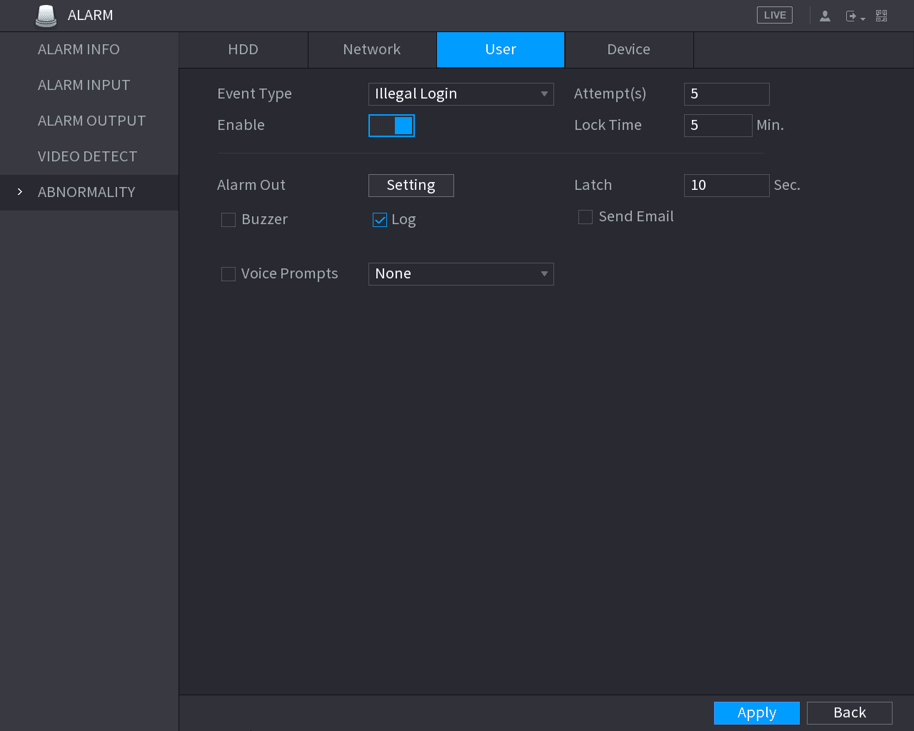
The User interface is displayed. See Figure 5-137.
Configure the User event
Configure the settings for the User event. See Table 5-43.
| Parameter | Description |
|---|---|
| Event Type | In the Event Type list, select Illegal Login. |
| Enable | Enable the user error detection function. If you do not enable this function, there will be no limit for wrong password entry and the account cannot be locked because of the wrong password. |
| Attempt(s) | Set the maximum number of allowable wrong password entries. The account will be locked after your entries exceed the maximum number. |
| Lock Time | Set how long the account is locked for. The value ranges from 1 minute to 60 minutes. |
| Alarm Out | Click Setting to display setting interface. General Alarm: Enable alarm activation through the alarm devices connected to the selected output port. External Alarm: Enable alarm activation through the connected alarm box. Wireless Siren: Enable alarm activation through devices connected by USB gateway or camera gateway. |
| Latch | Set a length of time for the Device to delay turning off alarm after the external alarm is cancelled. The value ranges from 10 seconds to 300 seconds, and the default value is 10 seconds. |
| Send Email | Select the Send Email check box to enable the system to send an email notification when an alarm event occurs. To use this function, make sure the email function is enabled in Main Menu > NETWORK > EMAIL. |
| Buzzer | Select the check box to activate a buzzer noise at the Device. |
| Log | Select the check box to enable the Device to record a local alarm log. |
| Voice Prompts | Select to enable audio broadcast/voice prompts in response to a user account alarm event. |
Apply
Click Apply to complete the settings.
Configuring Device Event Settings
Open the Device interface
Select Main Menu > ALARM > ABNORMITY > Device.
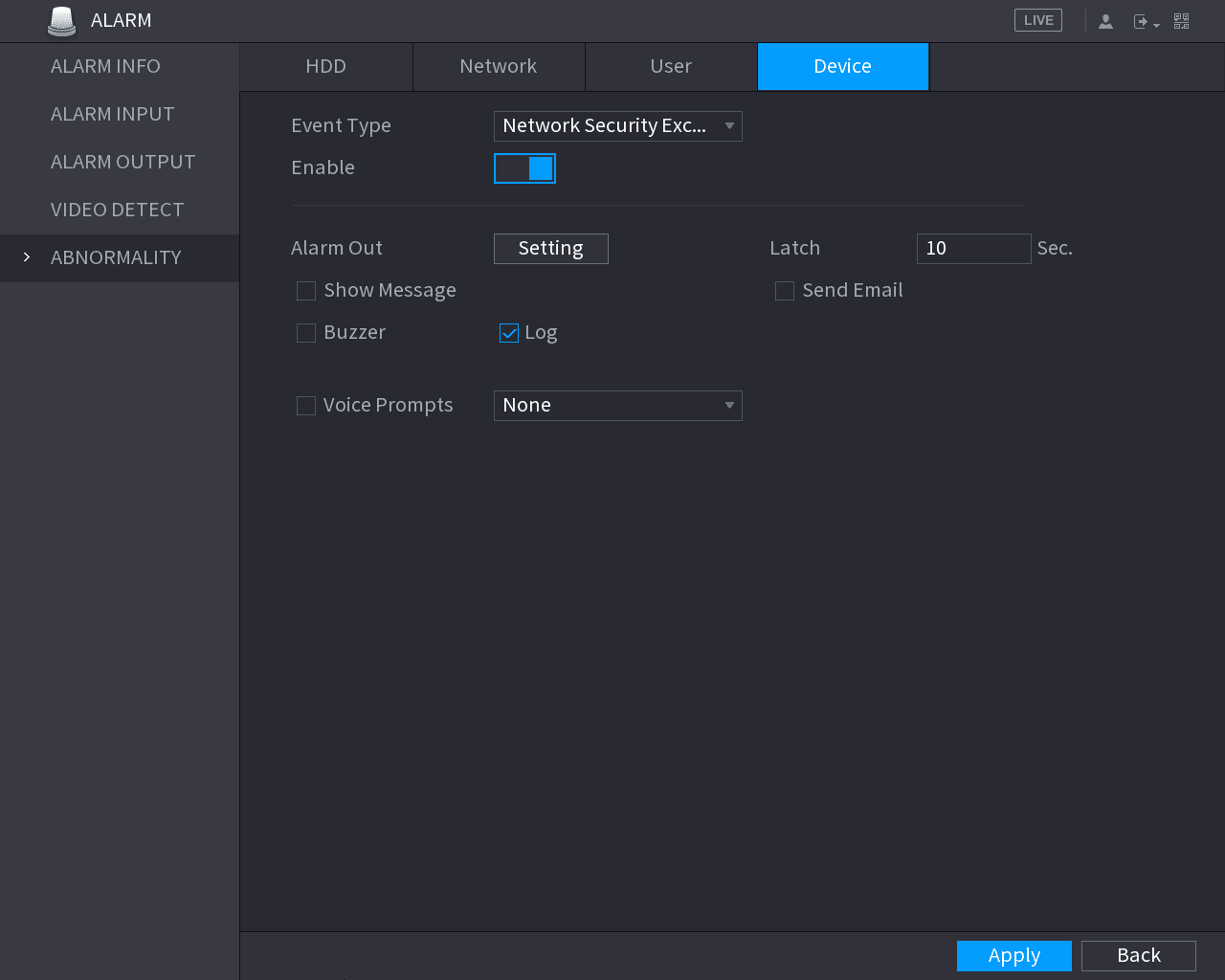
The Device interface is displayed. See Figure 5-138.
Configure the Device event
Configure the settings for the Device event. See Table 5-44.
| Parameter | Description |
|---|---|
| Event Type | In the Event Type list, select Network Security Exception, including brute force attack of Web path, brute force attack of session ID, session connection over-limit and abnormal program in trusted environment. |
Playing Back Video
Search for and play back recorded video and snapshots on the CVI DVR, including record control, instant playback, smart search, marking, splices, and the file list.
Smart Detection
Configure SMD, human face detection, and IVS smart detection on the CVI DVR to detect persons, vehicles, faces, and behaviors and trigger alarms.