 LTS Connect hjelpesenter
Introduction
Chapter 1 of the Turbo HD DVR GUI 4.0 user manual — front panel controls, IR remote control operations, USB mouse operation, and rear panel interfaces for all supported model variants.
Front Panel
The front panel varies according to different models. Please refer to the actual product.
DS-7100HQHI-K1
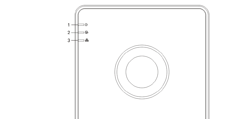
Figure 1-1 Front Panel of DS-7100HQHI-K1
Table 1-1 DS-7100HQHI-K1 Front Panel Description
| No. | Icon | Description |
|---|---|---|
| 1 | POWER | Turns red when DVR is powered up. |
| 2 | HDD | Turns red when data is being read from or written to HDD. |
| 3 | Network | Flickers blue when network connection is functioning properly. |
DS-7300HQHI-K4, DS-7300HUHI-K4, and iDS-7316HUHI-K4/16S

Figure 1-2 Front Panel of DS-7300HQHI-K4, DS-7300HUHI-K4, and iDS-7316HUHI-K4/16S
Table 1-2 DS-7300HQHI-K4 Front Panel Description
| No. | Name | Function Description |
|---|---|---|
| 1 | STATUS | Turns green when DVR is powered up. Turns green, indicating that the DVR is functioning properly. Turns green when device is controlled by an IR remote. Turns red when controlled by a keyboard and purple when IR remote and keyboard is used at the same time. |
| READY | Turns green, indicating that the DVR is functioning properly. | |
| ALARM | Turns red when a sensor alarm is detected. | |
| HDD | Flickers in red when data is being read from or written to HDD. | |
| Tx/Rx | Flickers in green when network connection is functioning properly. | |
| 2 | DVD-R/W | Slot for DVD-R/W. |
| 3 | Composite Keys — SHIFT | Switches between the numeric or letter input and functions of the composite keys. (Input letter or numbers when the light is out; Realize functions when the light is red.) |
| 1/MENU | Enters numeral "1"; Accesses the main menu interface. | |
| 2/ABC/F1 | Enters numeral "2"; Enters letters "ABC"; The F1 button when used in a list field will select all items in the list; Turns on/off PTZ light (if applicable) in PTZ Control mode; Use it to zoom out of the image. | |
| 3/DEF/F2 | Switches between main and spot video output in live view or playback mode. Enters numeral "3"; Enters letters "DEF"; Uses the F2 button to change the tab pages; Zooms in the image in PTZ control mode. | |
| 4/GHI/ESC | Enters numeral "4"; Enters letters "GHI"; Exits and back to the previous menu. | |
| 5/JKL/EDIT | Enters numeral "5"; Enters letters "JKL"; Deletes characters before cursor; Check the checkbox and select the ON/OFF switch; Starts/stops record clipping in playback. | |
| 6/MNO/PLAY | Enters numeral "6"; Enters letters "MNO"; Accesses to playback interface in Playback mode. | |
| 7/PQRS/REC | Enters numeral "7"; Enters letters "PQRS"; Accesses to manual record interface; Manually enables/disables record. | |
| 8/TUV/PTZ | Enters numeral "8"; Enters letters "TUV"; Accesses PTZ control interface. | |
| 9/WXYZ/PREV | Enters numeral "9"; Enters letters "WXYZ"; Multi-channel display in live view. | |
| 0/A | Enters numeral "0"; Shifts the input methods in the editing text field (upper and lowercase, alphabet, symbols or numeric input). | |
| 4 | DIRECTION | Navigates between different fields and items in menus. Uses the Up and Down buttons to speed up and slow down the playing of video files in Playback mode. The Left and Right button will select the next and previous record files. Cycles through channels in Live View mode. Controls the movement of the PTZ camera in PTZ control mode. |
| ENTER | Confirms selection in any of the menu modes. Checks the checkbox. Plays or pauses the playing of video files in Playback mode. Advances the video by a single frame in single-frame Playback mode. | |
| 5 | POWER | Power on/off switch. |
| 6 | JOG SHUTTLE Control | Moves the active selection up and down in a menu. Cycles through different channels in live view mode. Jumps 30s forward/backward in video files in the playback mode. Controls the movement of the PTZ camera in PTZ control mode. |
| 7 | USB Interface | Universal Serial Bus (USB) ports for additional devices such as USB mouse and USB Hard Disk Drive (HDD). |
| 8 | IR Receiver | Receiver for IR remote control. |
DS-8100HQHI/HUHI-K8

Figure 1-3 Front Panel of DS-8100HQHI/HUHI-K8
Table 1-3 DS-8100HQHI/HUHI-K8, DS-9000HUHI-K8, and iDS-9016HUHI-K8/16S Front Panel Description
| No. | Name | Function Description |
|---|---|---|
| 1 | STATUS | ALARM: Turns red when a sensor alarm is detected. READY: Turns blue, indicating that the DVR is functioning properly. STATUS: Turns blue when the device is controlled by an IR remote. Turns red when controlled by a keyboard and purple when IR remote and keyboard is used at the same time. MODEM: Flickers in blue when network connection is functioning properly. Tx/Rx: Turns blue when the device is in armed status; at this time, an alarm is enabled when an event is detected. GUARD: Turns off when the device is unarmed. The arm/disarm status can be changed by pressing and holding on the ESC button for more than 3 seconds in live view mode. Turns red when a sensor alarm is detected. |
| 2 | IR Receiver | Receiver for IR remote |
| 3 | Front Panel Lock | Lock or unlock the panel by the key. |
| 4 | DVD-R/W | Slot for DVD-R/W. |
| 5 | Alphanumeric Buttons | Switches to the corresponding channel in Live View or PTZ control mode. Inputs numbers and characters in edit mode. Switches between different channels in playback mode. Turns blue when the corresponding channel is recording; turns red when the channel is in network transmission status; turns pink when the channel is recording and transmitting. |
| 6 | USB Interfaces | Universal Serial Bus (USB) ports for such devices as USB mouse and USB Hard Disk Drive (HDD). |
| 7 | MAIN/SPOT/ZOOM- | Switches between main and spot video output in live view or playback mode. Selects all items on the list when used in a list field. Zooms out the image in PTZ control mode. |
| F1/LIGHT | Turns on/off PTZ light (if applicable) in PTZ control mode. Switches between play and reverse play in playback mode. | |
| F2/AUX | Cycles through tab pages. Switches between channels in synchronous playback mode. | |
| MENU/WIPER | Returns to the Main menu (after successful login). Presses and holds the button for five seconds to turn off audible key beep. Starts wiper (if applicable) in PTZ control mode. Shows/hides the control interface in playback mode. | |
| PREV/FOCUS- | Switches between single screen and multi-screen mode. Adjusts the focus in conjunction with the A/FOCUS+ button in PTZ control mode. | |
| PTZ/IRIS- | Enters the PTZ Control mode. Adjusts the iris of the PTZ camera in PTZ control mode. | |
| ESC | Returns to the previous menu. Presses for arming/disarming the device in live view mode. | |
| REC/SHOT | Presses this button followed by a numeric button to call a PTZ preset in PTZ control settings. Turns audio on/off in the playback mode. | |
| PLAY/AUTO | Enters the playback mode. Automatically scans in the PTZ control menu. | |
| ZOOM+ | Zooms in the PTZ camera in PTZ control setting. | |
| A/FOCUS+ | Adjusts focus in the PTZ Control menu. Switches between input methods (upper and lower case alphabet, symbols and numeric input). | |
| EDIT/IRIS+ | Edits text fields. When editing text fields, it also deletes the character in front of the cursor. Checks the checkbox in the checkbox fields. Adjusts the iris of the camera in PTZ control mode. | |
| 8 | DIRECTION | Navigates between different fields and items in menus. Uses the Up and Down buttons to speed up and slow down the playing of video files in Playback mode. The Left and Right button will select the next and previous record files. Cycles through channels in Live View mode. Controls the movement of the PTZ camera in PTZ control mode. |
| ENTER | Confirms selection in any of the menu modes. Checks the checkbox. Plays or pauses the playing of video files in Playback mode. Advances the video by a single frame in single-frame Playback mode. Stops/starts auto switch in Auto-switch mode. | |
| 9 | JOG SHUTTLE Control | Moves the active selection up and down in a menu. Cycles through different channels in live view mode. Jumps 30s forward/backward in video files in the playback mode. Controls the movement of the PTZ camera in PTZ control mode. |
| 10 | POWER ON/OFF | Power on/off switch. |
DS-9000HUHI-K8 and iDS-9016HUHI-K8/16S
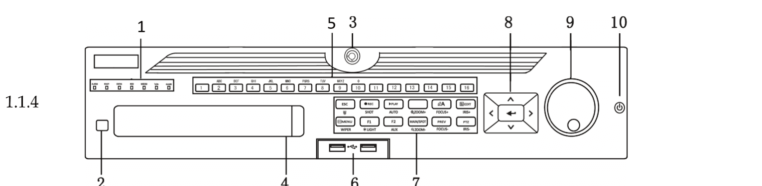
Figure 1-4 Front Panel of DS-9000HUHI-K8 and iDS-9016HUHI-K8/16S
The DS-9000HUHI-K8 and iDS-9016HUHI-K8/16S share the same front panel button layout and descriptions as the DS-8100HQHI/HUHI-K8. Refer to Table 1-3 above for the complete front panel description.
Other Models

Figure 1-5 Front Panel of Other Models
Table 1-4 Front Panel of Other Models Description
| No. | Icon | Description |
|---|---|---|
| 1 | POWER | Turns white when DVR is powered up. |
| 2 | HDD | Turns red when data is being read from or written to HDD. |
| 3 | Network | Flashes white when the network is well-connected. |
| 4 | IR | Receiver for IR remote control. |
| 5 | USB Interface | Universal Serial Bus (USB) ports for additional devices such as USB mouse and USB Hard Disk Drive (HDD). |
IR Remote Control Operations
The device may also be controlled with the included IR remote control as shown in Figure 1-6.
The IR remote is set at the factory to control the device (using default Device ID# 255) without any additional steps. Device ID# 255 is the default universal device identification number shared by the devices. You may also pair an IR Remote to a specific device by changing the Device ID#, as follows:
Pairing the IR Remote to a Specific Device (Optional)
You can pair an IR Remote to a specific device by creating a user-defined Device ID#. This feature is useful when using multiple IR Remotes and devices.
On the device
Go to System > General.
Check and remember device ID#
Check and remember device ID#. The default ID# is 255. This ID# is valid for all the IR remote controls.
On the IR Remote
Press DEV on the remote control.
Enter the device ID#
Enter the Device ID# you set in step 2.
Accept
Press Enter on the remote to accept the new Device ID#.
Unpairing (Disabling) an IR Remote from a Device
To unpair an IR Remote from a device so that the unit cannot control any device functions, proceed as follows:
Press the DEV key on the IR Remote. Any existing Device ID# will be erased from the unit's memory and it will no longer function with the device.
(Re)-enabling the IR Remote requires pairing to a device. See Pairing the IR Remote to a Specific Device (Optional) above.
The keys on the remote control closely resemble the ones on the front panel. See the table below.
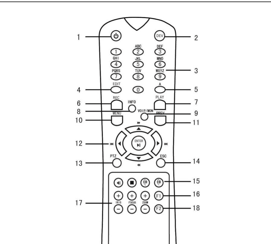
Figure 1-6 Remote Control
Table 1-5 IR Remote Functions
| No. | Name | Function Description |
|---|---|---|
| 1 | POWER ON/OFF | To Turn Power On: If User Has Not Changed the Default device ID# (255): Press Power On/Off button (1) down for five seconds to display the "Yes/No" verification prompt. Press Enter button (12) to accept selection. Start device. If User Has Changed the device ID#: Press DEV button. Use Number buttons to enter user-defined Device ID#. Press Enter button. Press Power button to start device. To Turn Device Off: If User Is Logged On: Hold Power On/Off button (1) down for five seconds to display the "Yes/No" verification prompt. Press the Enter button (12) to display the on-screen keyboard. Input the user name. Press the Down Arrow button (12) to move to the "Password" field. Input password (use on-screen keyboard or numeric buttons for numbers). Press the Enter button (12) to input and dismiss the on-screen keyboard. Press the Yes/No verification prompt (use Up/Down Arrow buttons to move between fields). Press button (12) to accept selection. User name/password prompt depends on device configuration. See "System Configuration" section. |
| 2 | DEV | Enable IR Remote: Press DEV button, enter device ID# with number keys, press Enter to pair unit with device. Disable IR Remote: Press DEV button to disable Device ID#; unit will no longer be paired with the device. |
| 3 | Numerals | Switch to the corresponding channel in Live View or PTZ Control mode. Input numbers in edit mode. |
| 4 | EDIT | Delete characters before cursor. Check the checkbox and select the ON/OFF switch. |
| 5 | A | Adjust focus in the PTZ Control menu. Switch on-screen keyboards (upper and lower case alphabet, symbols, and numerals). |
| 6 | REC | Call a PTZ preset in PTZ control settings. Turn audio on/off in Playback mode. |
| 7 | PLAY | Go to Playback mode. Auto scan in the PTZ control menu. |
| 8 | INFO | Reserved. |
| 9 | VOIP | Switches between main and spot output. Zooms out the image in PTZ control mode. |
| 10 | MENU | Return to Main menu (after successful login). N/A. |
| 11 | PREV | Show/hide full screen in Playback mode. |
| 12 | DIRECTION | Navigate between fields and menu items. Use Up/Down buttons to speed up/slow down recorded video, and Left/Right buttons to advance/rewind 30 secs in Playback mode. Cycle through channels in Live View mode. Control PTZ camera movement in PTZ control mode. |
| ENTER | Confirm selection in any menu mode. | |
| 13 | PTZ | Enter PTZ Control mode. |
| 14 | ESC | Go back to previous screen. |
| 15 | RESERVED | N/A. |
| 16 | F2 | N/A. Switch between play and reverse play in Playback mode. |
| 17 | PTZ Control | Adjust PTZ camera iris, focus, and zoom. |
| 18 | F2 | Cycle through tab pages. Switch between channels in Synchronous Playback mode. |
Troubleshooting
Make sure you have installed batteries properly in the remote control. And you have to aim the remote control at the IR receiver in the front panel.
If there is no response after you press any button on the remote, follow the procedure below to troubleshoot.
Check the device ID#
Go to System > General by operating the front control panel or the mouse.
Verify device ID#
Check and remember device ID#. The default ID# is 255. This ID# is valid for all the IR remote controls.
Press ENTER on the remote
Press ENTER on the remote.
If the Status indicator on the front panel turns blue, the remote control is operating properly. If the Status indicator does not turn blue and there is still no response from the remote, please check the following:
- Batteries are installed correctly and the polarities of the batteries are not reversed.
- Batteries are fresh and not out of charge.
- IR receiver is not obstructed.
- No fluorescent lamp is used nearby.
If the remote still can't function properly, please change a remote and try again, or contact the device provider.
USB Mouse Operation
A regular 3-button (Left/Right/Scroll-wheel) USB mouse can also be used with this device. To use a USB mouse:
Plug USB mouse into one of the USB interfaces on the front panel of the device.
The mouse should automatically be detected. If in a rare case that the mouse is not detected, the possible reason may be that the two devices are not compatible, please refer to the recommended the device list from your provider.
Table 1-6 Description of the Mouse Control
| Name | Action | Description |
|---|---|---|
| Left-Click | Single-Click | Live view: Select channel and show the quick set menu. Menu: Select and enter. |
| Double-Click | Live view: Switch between single-screen and multi-screen. | |
| Click and Drag | PTZ control: pan, tilt and zoom. Video tampering, privacy mask and motion detection: Select target area. Digital zoom-in: Drag and select target area. Live view: Drag channel/time bar. | |
| Right-Click | Single-Click | Live view: Show menu. Menu: Exit current menu to upper level menu. |
| Scroll-Wheel | Scrolling up | Live view: Previous screen. Menu: Previous item. |
| Scrolling down | Live view: Next screen. Menu: Next item. |
Rear Panel
The rear panel varies according to different models. Please refer to the actual product. The following figures are for reference only.
DS-7100HQHI-K1
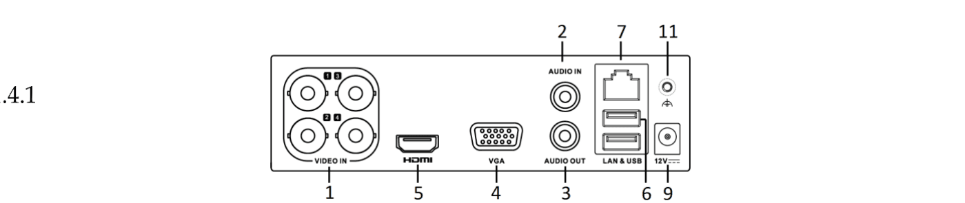
Figure 1-7 Rear Panel of DS-7100HQHI-K1
DS-7200HUHI-K and DS-7200HUHI-K/4S

Figure 1-8 Rear Panel of DS-7200HUHI-K and DS-7200HUHI-K/4S
DS-7200HUHI-K/P

Figure 1-9 Rear Panel of DS-7200HUHI-K/P
DS-7200HTHI-K1
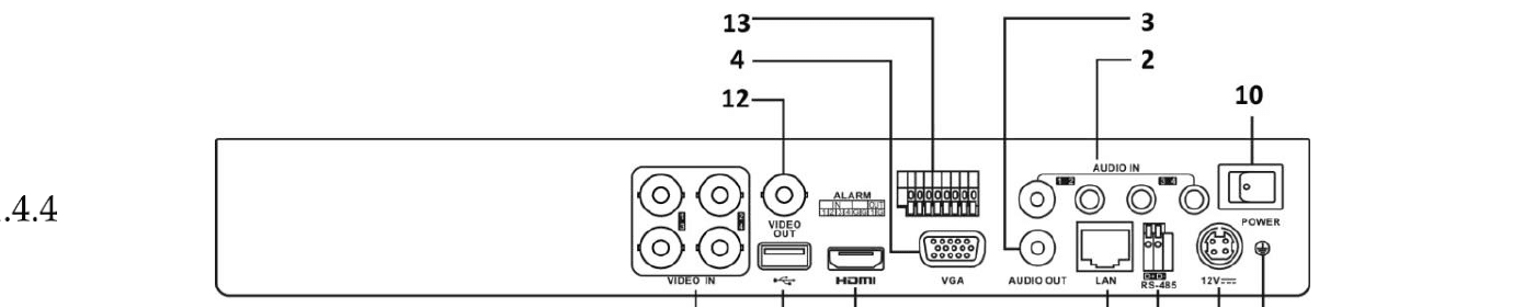
Figure 1-10 Rear Panel of DS-7200HTHI-K1
DS-7200HTHI-K2

Figure 1-11 Rear Panel of DS-7200HTHI-K2
DS-7200HQHI-K (with 16 Video Inputs), iDS-7200HQHI-K/4S

Figure 1-12 Rear Panel of DS-7200HQHI-K (with 16 Video Inputs)
Table 1-7 Description of DS-7200HQHI-K/P Rear Panel
| No. | Item | Description |
|---|---|---|
| 1 | VIDEO IN | BNC interface for Turbo HD and analog video input. |
| 2 | AUDIO IN | RCA connector |
| 3 | AUDIO OUT | RCA connector. |
| 4 | VGA | DB15 connector for VGA output. Display local video output and menu. |
| 5 | HDMI | HDMI video output connector. |
| 6 | USB Interface | Universal Serial Bus (USB) port for additional devices. |
| 7 | Network Interface | Connector for network. |
| 8 | RS-485 Interface | Connector for RS-485 devices. |
| 9 | Power Supply | 48 VDC or 12 VDC. |
| 10 | Power Switch | Switch for turning on/off the device. |
| 11 | GND | Ground |
| 12 | VIDEO OUT | BNC connector for video output. |
| 13 | Alarm In/Out | Connector for alarm input and output. |
DS-7300HQHI-K (with 16 Video Inputs)

Figure 1-13 Rear Panel of DS-7300HQHI-K (with 16 Video Inputs)
Table 1-8 Description of DS-7300HQHI-K Rear Panel
| No. | Item | Description |
|---|---|---|
| 1 | VIDEO IN | BNC interface for Turbo HD and analog video input. |
| 2 | VIDEO OUT | BNC connector for video output. |
| 3 | AUDIO IN | RCA connector. |
| 4 | USB Port | Universal Serial Bus (USB) port for additional devices. |
| 5 | HDMI | HDMI video output connector. |
| 6 | VGA | DB15 connector for VGA output. Display local video output and menu. |
| 7 | AUDIO OUT | RCA connector. |
| 8 | Network Interface | Connector for network. |
| 9 | RS-485 and Alarm Interface | Connector for RS-485 devices. T+ and T- pins connect to R+ and R- pins of PTZ receiver respectively. D+, D- pin connects to Ta, Tb pin of controller. For cascading devices, the first DVR's D+, D- pin should be connected with the D+, D- pin of the next DVR. Connector for alarm input. Connector for alarm output. |
| 10 | Power Supply | 100 to 240 VAC power supply. |
| 11 | Power Switch | Switch for turning on/off the device. |
| 12 | GND | Ground |
| 13 | LINE IN | BNC connector for audio input. |
| 14 | eSATA | Connects external SATA HDD, CD/DVD-RW. |
| 15 | RS-232 Interface | Connector for RS-232 devices. |
DS-7300HUHI-K4 and iDS-7316HUHI-K4/16S (with 16 Video Inputs)

Figure 1-14 Rear Panel of DS-7300HUHI-K4 and iDS-7316HUHI-K4/16S (with 16 Video Inputs)
DS-9000HUHI-K8 (with 8 Video Inputs)
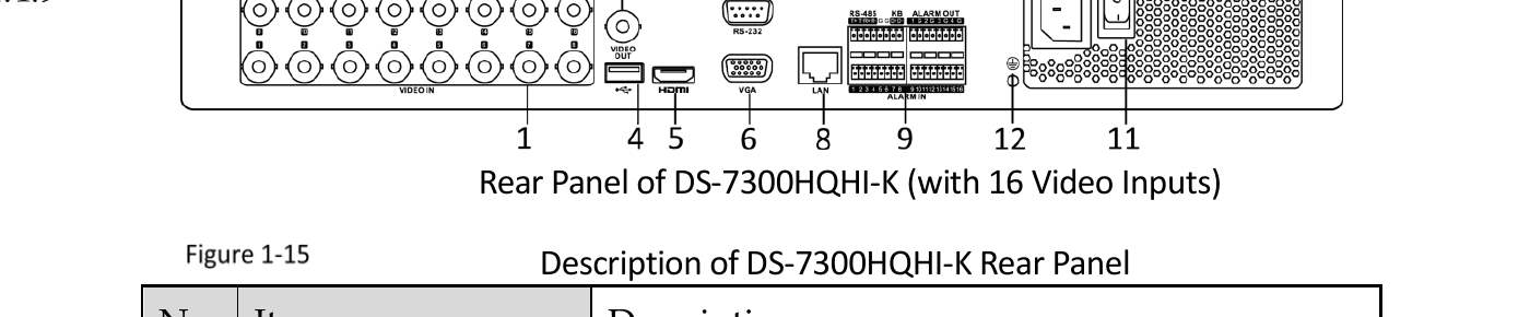
Figure 1-15 Rear Panel of DS-9000HUHI-K8 (with 8 Video Inputs)
Table 1-9 Description of DS-7300HUHI-K4/DS-9000HUHI-K8 Rear Panel
| No. | Item | Description |
|---|---|---|
| 1 | VIDEO IN | BNC interface for Turbo HD and analog video input. |
| 2 | VIDEO OUT | BNC connector for video output. |
| 3 | AUDIO IN/LOOP OUT (for DS-9000HUHI-K8) | RCA connector |
| 4 | USB Port | Universal Serial Bus (USB) port for additional devices. |
| 5 | HDMI1/VGA | Simultaneous HDMI1/VGA output. Display local video output and menu. |
| 6 | HDMI2 | HDMI2 video output connector. |
| 7 | AUDIO OUT | RCA connector. |
| 8 | Network Interface | Connector for network |
| 9 | RS-485 and Alarm Interface | Connector for RS-485 devices. T+ and T- pins connect to R+ and R- pins of PTZ receiver respectively. D+, D- pin connects to Ta, Tb pin of controller. For cascading devices, the first DVR's D+, D- pin should be connected with the D+, D- pin of the next DVR. Connector for alarm input. Connector for alarm output. |
| 10 | Power Supply | 100 to 240 VAC power supply. |
| 11 | Power Switch | Switch for turning on/off the device. |
| 12 | GND | Ground |
| 13 | LINE IN | BNC connector for audio input. |
| 14 | eSATA | Connects external SATA HDD, CD/DVD-RW. |
| 15 | RS-232 Interface | Connector for RS-232 devices. |
| 16 | ALARM OUT | Connector for alarm output. |
| 17 | AUDIO IN | DB26 female head |
DS-7300HQHI-K4 (with 32-ch Video Inputs)
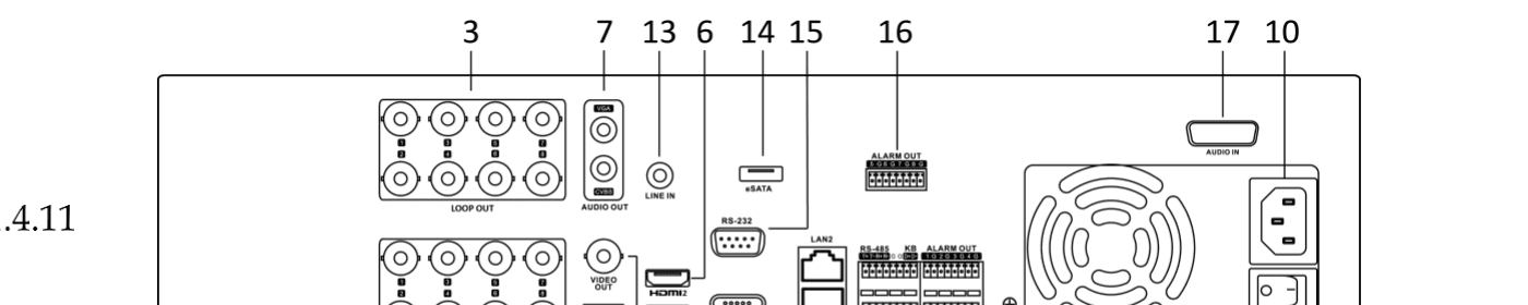
Figure 1-16 Rear Panel of DS-7300HQHI-K4 (with 32-ch Video Inputs)
DS-7300HUHI-K4 (with 32-ch Video Inputs)

Figure 1-17 Rear Panel of DS-7300HUHI-K4 (with 32-ch Video Inputs)
DS-8100HQHI/HUHI-K8 (with 32-ch Video Inputs)

Figure 1-18 Rear Panel of DS-8100HQHI/HUHI-K8 (with 32-ch Video Inputs)
DS-9000HUHI-K8 (with 32-ch Video Inputs)

Figure 1-19 Rear Panel of DS-9000HUHI-K8 (with 32-ch Video Inputs)
DS-9000HUHI-K8 (with 32-ch Video Inputs) — Variant

Figure 1-21 Rear Panel of DS-9000HUHI-K8 (with 32-ch Video Inputs)
iDS-9016HUHI-K8/16S
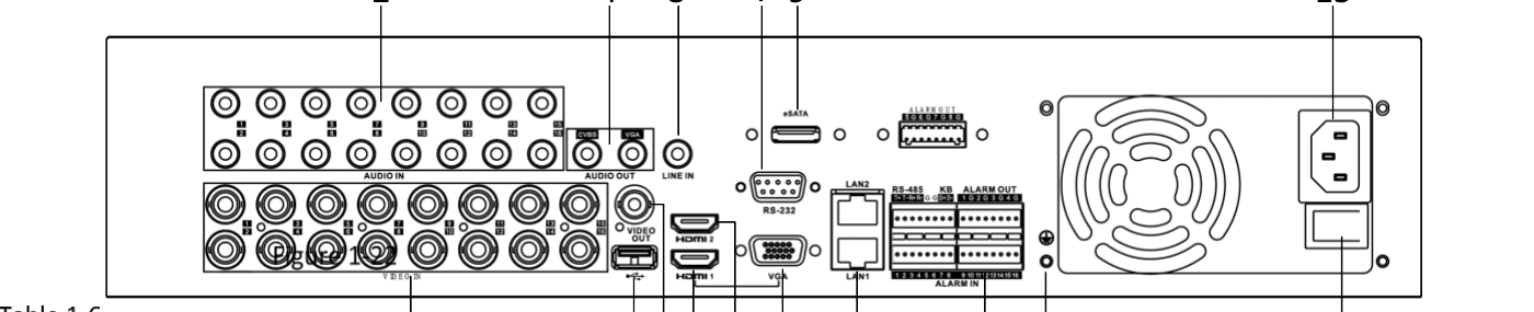
Figure 1-22 Rear Panel of iDS-9016HUHI-K8/16S
Table 1-10 Description of DS-7300HQHI-K8, DS-7300HQHI/HUHI-K4, DS-8100HQHI/HUHI-K8, DS-9000HUHI-K8, and iDS-9016HUHI-K8/16S Rear Panel
| No. | Item | Description |
|---|---|---|
| 1 | VIDEO IN | BNC interface for Turbo HD and analog video input. |
| 2 | AUDIO IN | RCA connector. |
| 3 | LINE IN | BNC connector for audio input. |
| 4 | AUDIO OUT | RCA connector. |
| 5 | VIDEO OUT | BNC connector for video output. |
| 6 | RS-485 and Alarm Interface | Connector for RS-485 devices. T+ and T- pins connect to R+ and R- pins of PTZ receiver respectively. D+, D- pin connects to Ta, Tb pin of controller. For cascading devices, the first DVR's D+, D- pin should be connected with the D+, D- pin of the next DVR. Connector for alarm input. Connector for alarm output. |
| 7 | RS-232 Interface | Connector for RS-232 devices. |
| 8 | VGA Interface | VGA video output connector. Display local video output and menu. |
| 9 | eSATA | Connects external SATA HDD, CD/DVD-RW. |
| 10 | HDMI1 Interface | HDMI1 video output connector. Display local video output and menu. |
| 11 | HDMI2 Interface | HDMI2 video output connector. |
| 12 | Network Interface | Connector for network. |
| 13 | USB Interface | Universal Serial Bus (USB) port for additional devices. |
| 14 | GND | Ground |
| 15 | Power Supply | 100 to 240 VAC power supply. |
| 16 | Power Switch | Switch for turning on/off the device. |
| 17 | AUDIO IN | DB26 female head |
Turbo HD DVR User Manual (GUI 4.0)
Complete user manual for the LTS Platinum Series Turbo HD DVR running the GUI 4.0 local interface — hardware panels, activation, cameras, PTZ, storage, playback, events, VCA, smart analysis, network, and system maintenance.
Getting Started
First-time setup guide covering device activation, security questions, unlock pattern, login methods, the setup wizard, the main menu, and basic system operations for the Turbo HD DVR GUI 4.0.