 Center za pomoč LTS Connect
Event Manager
Search and back up alarm logs, view alarm status, configure alarm input and output, set up video detection, audio detect, thermal alarm, and abnormality events on the Sapphire Series NVR.
Alarm Info
You can search, view and back up the alarm information.
Open the Alarm Info interface
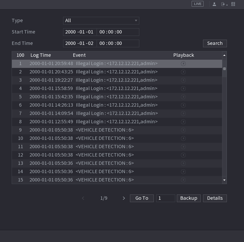
Select Main Menu > ALARM > ALARM INFO. The ALARM INFO interface is displayed. See the figure below.
Select the event type and time range
In the Type list, select the event type; in the Start Time box and End Time box, enter the specific time.
Search
Click Search. The search results are displayed.
Back up the results
Click Backup to back up the search results into the external storage device.
- Select an alarm event log and then click Backup to back up it to peripheral USB device.
- Select an alarm event log, click the play icon to play the recorded video of alarm event. Double-click a log or click Details to view the detailed information of the event.
Alarm Status
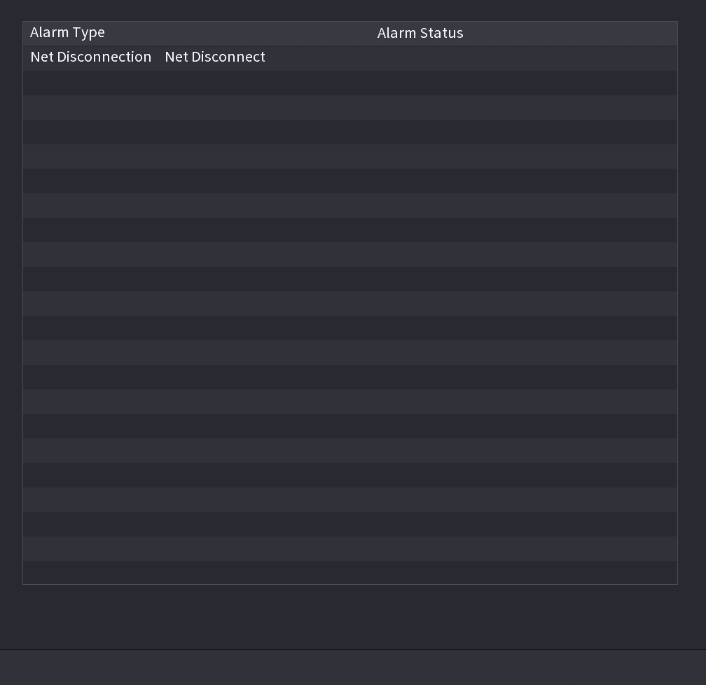
You can view NVR alarm event, and remote channel alarm event.
Select Main Menu > ALARM > ALARM STATUS, the ALARM STATUS interface is displayed. See the figure below.
Alarm Input
Open the Alarm Input interface
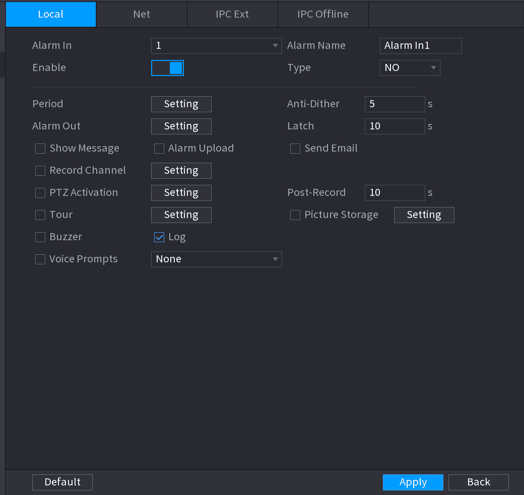
Select Main menu > ALARM > ALARM INPUT. The ALARM INPUT interface is displayed. See the figure below.
Understand the four alarm types
There are four alarm types.
- Local alarm: After connect the alarm device to the NVR alarm input port, system can trigger the corresponding alarm operations when there is alarm signal from the alarm input port to the NVR.
- Network alarm: NVR trigger corresponding alarm operations when it receives the alarm signal via the network transmission.
- IPC external alarm: When the network camera connected peripheral device has triggered an alarm, it can upload the alarm signal to the NVR via the network transmission. The system can trigger the corresponding alarm operations.
- IPC offline alarm: When the network connection between the NVR and the network camera is off, the system can trigger the corresponding alarm operations.
Enable the channel
Set Alarm In channel number and then select the Enable check box to enable the function.
Configure parameters
Configure parameters. See the table below.
| Parameter | Description |
|---|---|
| Alarm in | Select a channel to set alarm. |
| Enable | Check the box to enable the function. |
| Alarm Name | Enter an alarm name. |
| Type | NO (normal open) or NC (normal close). |
| Period | Define a period during which the alarm is active. For details, see Setting Period in 4.8.5.1 Motion Detect. |
| Alarm Out | The alarm device (such as lights, sirens, etc.) is connected to the alarm output port. When an alarm occurs, the NVR device transmits the alarm information to the alarm device. |
| Latch | When the alarm ends, the alarm extended for a period of time. The time range is from 0 seconds to 300 seconds. |
| Show Message | Check box to enable a pop-up message in your local host PC. |
| Alarm Upload | Select the check box. When an alarm occurs, the NVR device uploads an alarm signal to the network (including the alarm center). This function is for some series products only. You need to set the alarm center first. For details, see 4.12.9 Alarm Centre. |
| Send Email | Select the check box. When an alarm occurs, the NVR device sends an email to the set mailbox to notify the user. You need to set the email first. For details, see 4.12.6 Email. |
| Record Channel | Select the check box and select the needed recording channel (support multiple choices). When an alarm occurs, the NVR device activates the channel for recording. You need to enable intelligent recording and auto recording first. For details, see 4.1.4.6 Schedule. |
| PTZ Activation | Select the check box and click Setting to select the channel and PTZ action. When an alarm occurs, the NVR device associates the channel to perform the corresponding PTZ action. For example, activate the PTZ in channel one to turn to the preset point X. Tripwire alarm supports to activate PTZ preset point only. You need to set the corresponding PTZ actions first, see 4.4.3 Configuring PTZ Functions. |
| Delay | At the end of the alarm, the recording extends for a period of time. The time range is from 10 seconds to 300 seconds. |
| Tour | Select the check box and select the channel for tour. When an alarm occurs, the local interface of the NVR device displays the selected channel screen. You need to set the time interval and mode for tour first, see 4.16.2 Tour. After the tour is over, the preview interface is restored to the screen split mode before the tour. |
| Log | Select the check box, the NVR device records the alarm information in the log when an alarm occurs. |
| Voice Prompts | Check the box and then select the corresponding audio file from the dropdown list. System plays the audio file when the alarm occurs. Refer to 4.17.1 File Manage to add audio file first. |
| Buzzer | Select the check box to activate the buzzer when an alarm occurs. |
| Record Channel | Select the check box and select the needed recording channel (support multiple choices). When an alarm occurs, the NVR device activates the channel for recording. You need to enable intelligent recording and auto recording first. For details, see 4.1.4.6 Schedule. |
Save
Click Apply.
Alarm Control
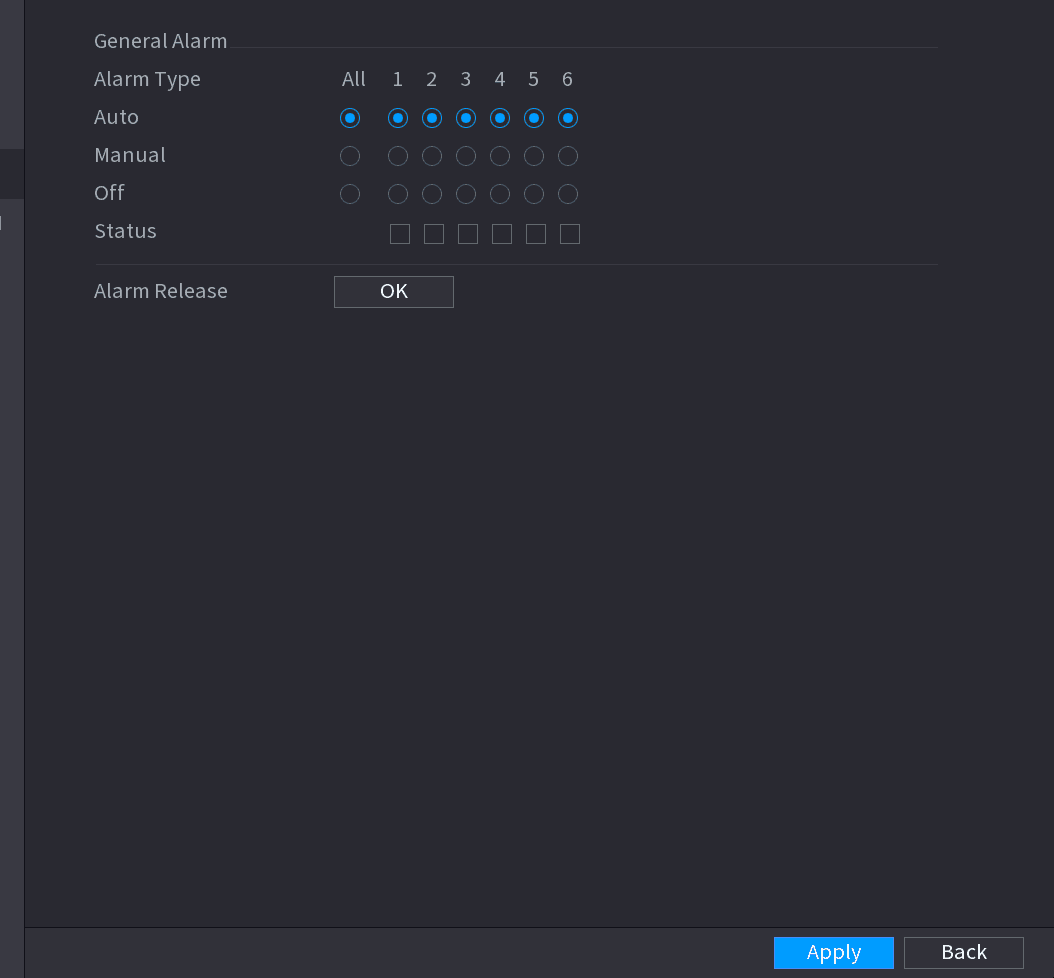
You can set proper alarm output (Auto/manual/off). Connect the alarm device to the system alarm output port, and set the mode as auto, system can trigger the corresponding operations when an alarm occurs.
- Auto: Once an alarm event occurs, system can generate an alarm.
- Manual: Alarm device is always on the alarming mode.
- Off: Disable alarm output function.
Open the Alarm Output interface
Select Main Menu > ALARM > ALARM OUTPUT. The ALARM OUTPUT interface is displayed. See the figure below.
Select the alarm mode
Select the alarm mode of the alarm output channel.
- Click OK button of the Alarm Release, you can clear all alarm output statuses.
- View the alarm output status on the Status column.
Save
Click Apply.
Video Detection
The video detection adopts the computer image and graphics process technology. It can analyze the video and check there is considerable changing or not. Once video has changed considerably (such as there is any moving object, video is distorted), system can trigger the corresponding alarm activation operations.
Select Main menu > ALARM > VIDEO DETECTION > MOTION DETECT, you can see motion detect interface. There are five detection types: motion detection, video loss, tampering, scene changing and PIR alarm.
Motion Detect
When the moving object appears and moves fast enough to reach the preset sensitivity value, the system activates the alarm.
Open the Motion Detect interface
Select Main Menu > ALARM > VIDEO DETECTION > Motion Detect. The Motion Detect interface is displayed. See the figure below.
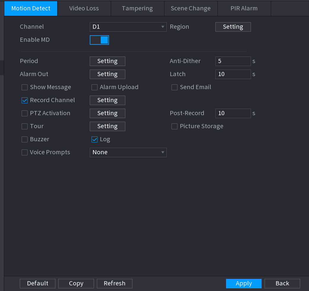
Configure parameters
Configure the settings for the motion detection parameters. See the table below.
| Parameter | Description |
|---|---|
| Channel | In the Channel list, select a channel to set the motion detection. |
| Region | Click Setting to define the motion detection region. |
| Enable MD | Enable or disable the motion detection function. Check the box to enable the function. |
| Period | Define a period during which the motion detection is active. |
| Sensitivity | The higher the value is, the easier it is to trigger an alarm. But at the same time, the false alarm may occur. The default value is recommended. |
| Alarm Out | The alarm device (such as lights, sirens, etc.) is connected to the alarm output port. When an alarm occurs, the NVR device transmits the alarm information to the alarm device. |
| Latch | When the alarm ends, the alarm extended for a period of time. The time range is from 0 seconds to 300 seconds. |
| Show Message | Check box to enable a pop-up message in your local host PC. |
| Alarm Upload | Select the check box. When an alarm occurs, the NVR device uploads an alarm signal to the network (including the alarm center). This function is for some series products only. You need to set the alarm center first. For details, see 4.12.9 Alarm Centre. |
| Send Email | Select the check box. When an alarm occurs, the NVR device sends an email to the set mailbox to notify the user. You need to set the email first. For details, see 4.12.6 Email. |
| Record Channel | Select the check box and select the needed recording channel (support multiple choices). When an alarm occurs, the NVR device activates the channel for recording. You need to enable intelligent recording and auto recording first. For details, see 4.1.4.6 Schedule. |
| PTZ Activation | Select the check box and click Setting to select the channel and PTZ action. When an alarm occurs, the NVR device associates the channel to perform the corresponding PTZ action. For example, activate the PTZ in channel one to turn to the preset point X. Tripwire alarm supports to activate PTZ preset point only. You need to set the corresponding PTZ actions first, see 4.4.3 Configuring PTZ Functions. |
| Delay | At the end of the alarm, the recording extends for a period of time. The time range is from 10 seconds to 300 seconds. |
| Tour | Select the check box and select the channel for tour. When an alarm occurs, the local interface of the NVR device displays the selected channel screen. You need to set the time interval and mode for tour first, see 4.16.2 Tour. After the tour is over, the preview interface is restored to the screen split mode before the tour. |
| Snapshot | Select the Snapshot check box to take a snapshot of the selected channel. To use this function, select Main Menu > CAMERA > ENCODE > Snapshot, in the Mode list, select Event (Trigger). |
| Voice Prompts | Check the box and then select the corresponding audio file from the dropdown list. System plays the audio file when the alarm occurs. Refer to 4.17.1 File Manage to add audio file first. |
| Buzzer | Select the check box to activate the buzzer when an alarm occurs. |
Save the settings
Click Apply to save the settings.
- Click Default to restore the default setting.
- Click Copy, in the Copy dialog box, select the additional channel(s) that you want to copy the motion detection settings to, and then click Apply.
- Click Test to test the settings.
Setting the Motion Detection Region
Open the region setting screen
Next to Region, click Setting. The region setting screen is displayed.
Display the setting interface
Point to the middle top of the interface. The setting interface is displayed. See the figure below.
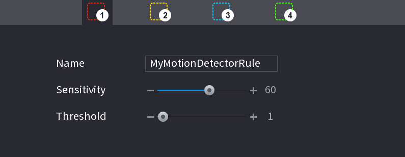
Configure the regions
Configure the regions settings. You can configure totally four regions.
- Select one region, for example, click region 1.
- Drag on the screen to select the region that you want to detect.
- The selected area shows the color that represents the region.
- Configure the parameters. See the table below.
| Parameter | Description |
|---|---|
| Name | Enter a name for the region. |
| Sensitivity | Every region of every channel has an individual sensitivity value. The bigger the value is, the easier the alarms can be activated. |
| Threshold | Adjust the threshold for motion detect. Every region of every channel has an individual threshold. |
When anyone of the four regions activates motion detect alarm, the channel where this region belongs to will activate motion detect alarm.
Exit the region setting interface
Right-click on the screen to exit the region setting interface.
Complete the settings
On the Motion Detect interface, click Apply to complete the settings.
Setting Period
The system only activates the alarm in the defined period.
Open the Setting interface
Next to Period, click Setting. The Setting interface is displayed. See the figure below.
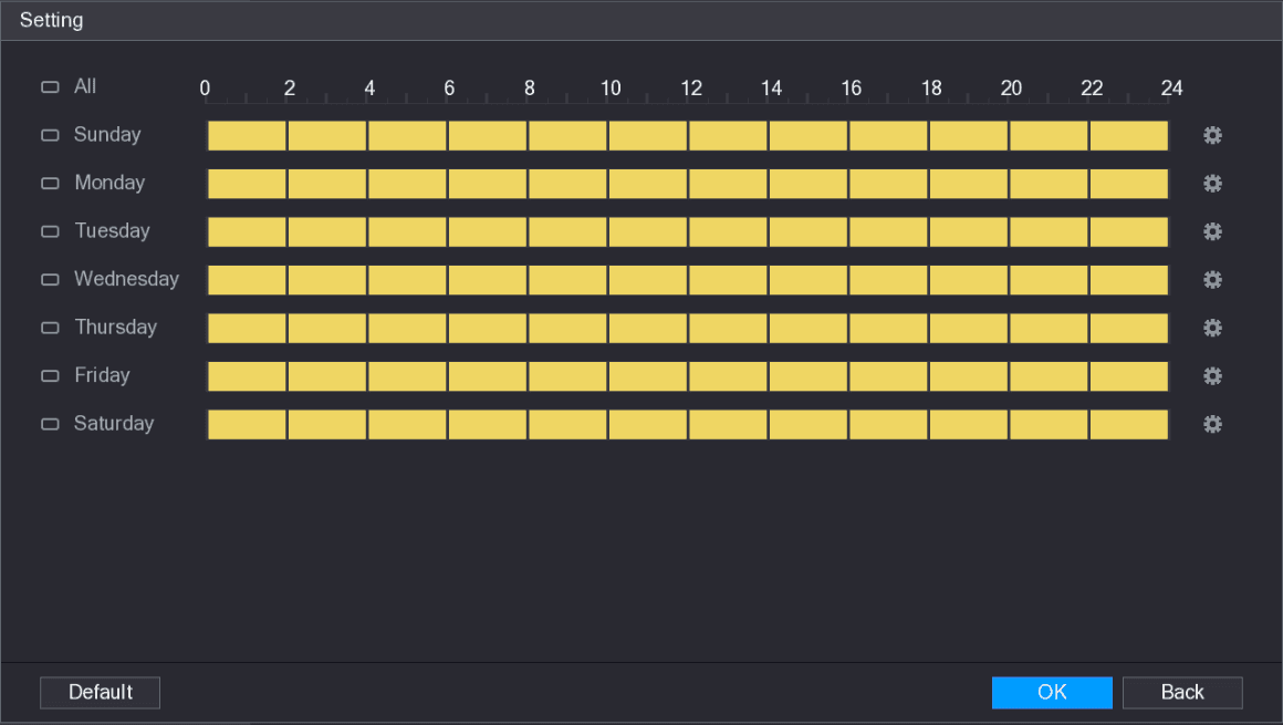
Define the motion detection period
Define the motion detection period. By default, it is active all the time.
- Define the period by drawing.
- Define for a specified day of a week: On the timeline, click the half-hour blocks to select the active period.
- Define for several days of a week: Click the checkbox before each day, the icon switches to the selected state. On the timeline of any selected day, click the half-hour blocks to select the active periods, all the selected days will take the same settings.
- Define for all days of a week: Click All, all day checkboxes switch to the selected state. On the timeline of any day, click the half-hour blocks to select the active periods, all the days will take the same settings.
- Define the period by editing. Take Sunday as an example.
-
Click the edit icon. The Period interface is displayed. See the figure below.
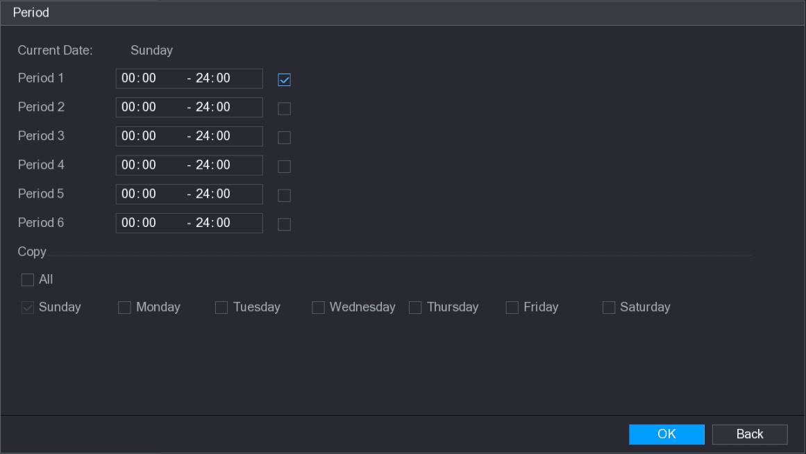
-
Enter the time frame for the period, and then select the check box to enable the settings.
- There are six periods for you to set for each day.
- Under Copy, select All to apply the settings to all the days of a week, or select specific day(s) that you want to apply the settings to.
-
Click OK to save the settings.
Complete the settings
On the Motion Detect interface, click Apply to complete the settings.
Tampering
When the camera lens is covered, or the video is displayed in a single color because of sunlight status, the monitoring cannot be continued normally. To avoid such situations, you can configure the tampering alarm settings.
Open the Tampering interface
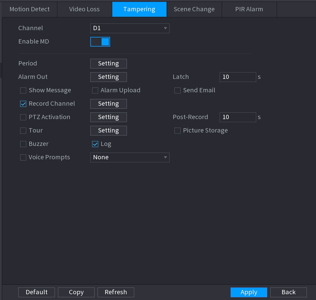
Select Main Menu > ALARM > VIDEO DETECTION > Tampering. The Tampering interface is displayed. See the figure below.
Configure parameters
To configure the settings for the tampering detection parameters, see 4.8.5.1 Motion Detect.
The Tampering function does not have region and sensitivity items.
Complete the settings
Click Apply to complete the settings.
- Click Default to restore the default setting.
- Click Copy, in the Copy dialog box, select the additional channel(s) that you want to copy the motion detection settings to, and then click Apply.
Video Loss
When the video loss occurs, the system activates the alarm.
Open the Video Loss interface
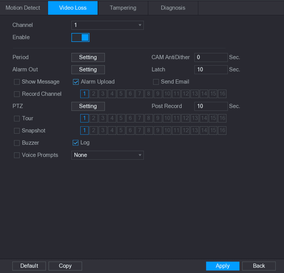
Select Main Menu > ALARM > VIDEO DETECTION > Video Loss. The Video Loss interface is displayed. See the figure below.
Configure parameters
To configure the settings for the video loss detection parameters, see 4.8.5.1 Motion Detect.
The video loss function does not have region and sensitivity items.
Complete the settings
Click Apply to complete the settings.
- Click Default to restore the default setting.
- Click Copy, in the Copy dialog box, select the additional channel(s) that you want to copy the motion detection settings to, and then click Apply.
Scene Change
When the detected scene has changed, system can generate an alarm.
Open the Scene Change interface
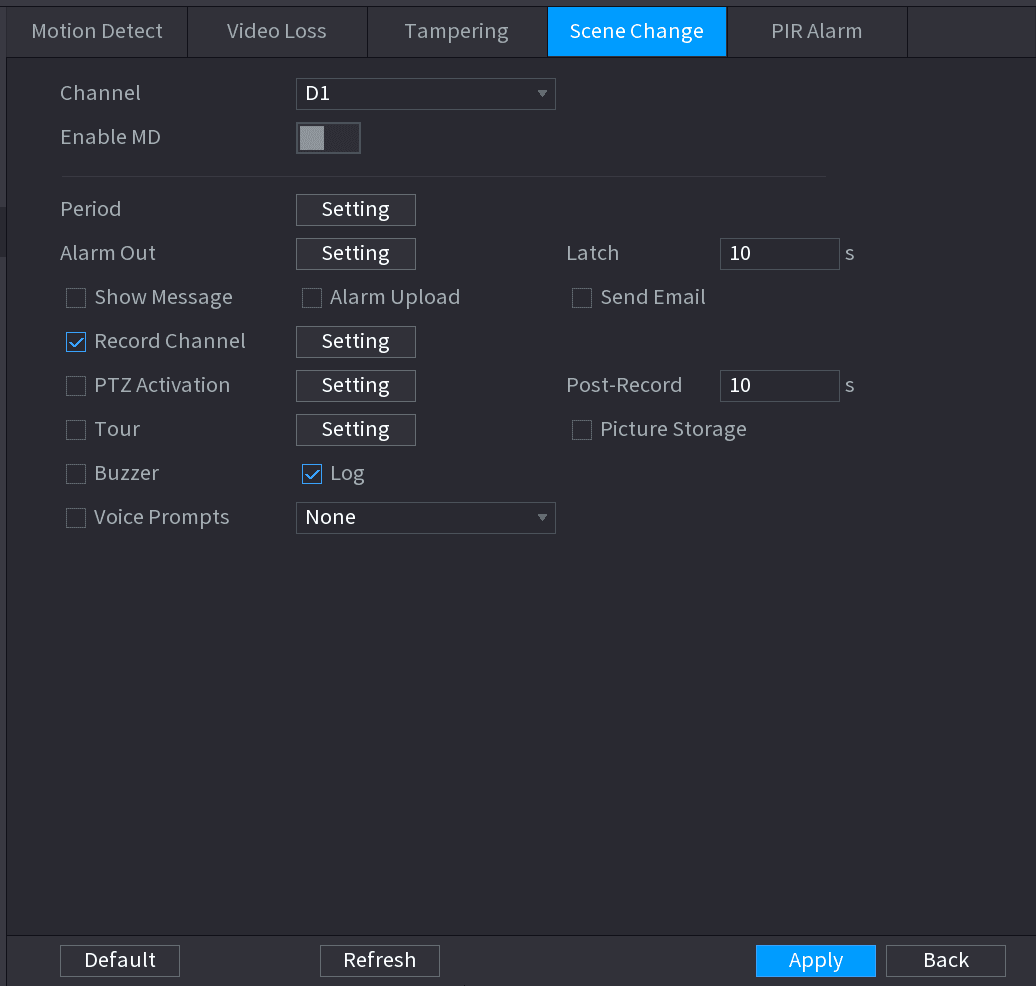
Select Main Menu > ALARM > VIDEO DETECTION > SCENE CHANGE. The Scene Change interface is displayed. See the figure below.
Configure parameters
To configure the settings for the scene change parameters, see 4.8.5.1 Motion Detect.
The scene change function does not have region and sensitivity items.
Complete the settings
Click Apply to complete the settings.
- Click Default to restore the default setting.
- Click Copy, in the Copy dialog box, select the additional channel(s) that you want to copy the motion detection settings to, and then click Apply.
PIR Alarm
When the detected scene has changed, system can generate an alarm.
PIR function helps enhancing the accuracy and validity of motion detect. It can filter the meaningless alarms that are activated by the objects such as falling leaves, flies. The detection range by PIR is smaller than the field angle.
PIR function is enabled by default if it is supported by the cameras. Enabling PIR function will get the motion detect to be enabled automatically to generate motion detection alarms; if the PIR function is not enabled, the motion detect just has the general effect.
Open the PIR Alarm interface
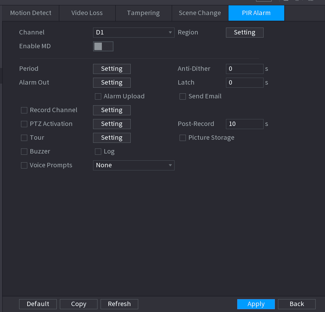
Select Main Menu > ALARM > VIDEO DETECT > PIR ALARM. The PIR Alarm interface is displayed. See the figure below.
Configure parameters
To configure the settings for the PIR alarm parameters, see 4.8.5.1 Motion Detect.
Complete the settings
Click Apply to complete the settings.
- Click Default to restore the default setting.
- Click Copy, in the Copy dialog box, select the additional channel(s) that you want to copy the motion detection settings to, and then click Apply.
Audio Detect
System can generate an alarm once it detect the audio is not clear, the tone color has changed or there is abnormal or audio volume changes.
Open the Audio Detect interface
Select Main Menu > ALARM > AUDIO DETECT. The AUDIO DETECT interface is displayed. See the figure below.
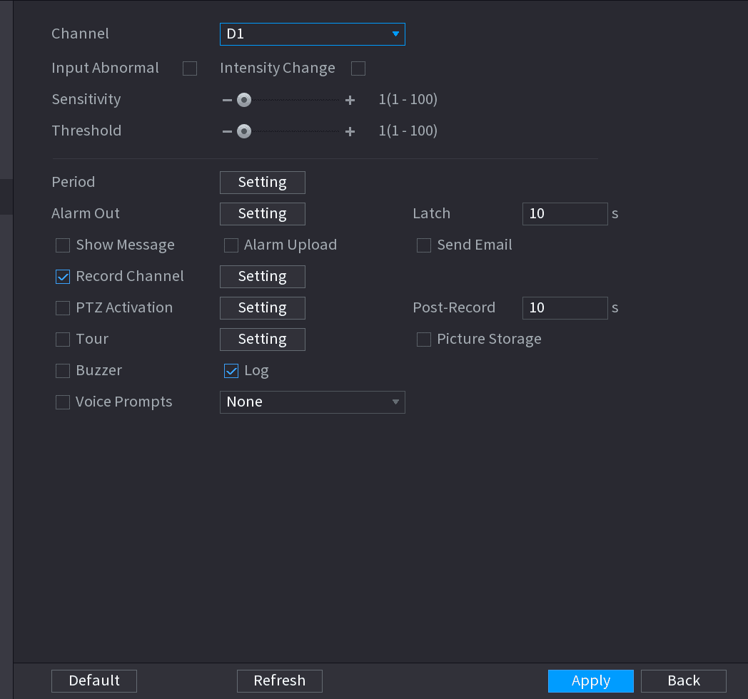
Configure parameters
Configure parameters. See the table below.
| Parameter | Description |
|---|---|
| Channel | In the Channel list, select a channel to set. |
| Input abnormal | Check the box here, system can generate an alarm once the audio input is abnormal. |
| Intensity change | Check the box here, system can generate an alarm once the audio volume becomes strong. |
| Period | Define a period during which the function is active. |
| Sensitivity | The higher the value is, the easier it is to trigger an alarm. But at the same time, the false alarm may occur. The default value is recommended. |
| Threshold | You can set intensity change threshold. The smaller the value is, the higher the sensitivity is. |
| Alarm Out | The alarm device (such as lights, sirens, etc.) is connected to the alarm output port. When an alarm occurs, the NVR device transmits the alarm information to the alarm device. |
| Latch | When the alarm ends, the alarm extended for a period of time. The time range is from 0 seconds to 300 seconds. |
| Show Message | Check box to enable a pop-up message in your local host PC. |
| Alarm Upload | Select the check box. When an alarm occurs, the NVR device uploads an alarm signal to the network (including the alarm center). This function is for some series products only. You need to set the alarm center first. For details, see 4.12.9 Alarm Centre. |
| Send Email | Select the check box. When an alarm occurs, the NVR device sends an email to the set mailbox to notify the user. You need to set the email first. For details, see 4.12.6 Email. |
| Record Channel | Select the check box and select the needed recording channel (support multiple choices). When an alarm occurs, the NVR device activates the channel for recording. You need to enable intelligent recording and auto recording first. For details, see 4.1.4.6 Schedule. |
| PTZ Activation | Select the check box and click Setting to select the channel and PTZ action. When an alarm occurs, the NVR device associates the channel to perform the corresponding PTZ action. For example, activate the PTZ in channel one to turn to the preset point X. Tripwire alarm supports to activate PTZ preset point only. You need to set the corresponding PTZ actions first, see 4.4.3 Configuring PTZ Functions. |
| Delay | At the end of the alarm, the recording extends for a period of time. The time range is from 10 seconds to 300 seconds. |
| Tour | Select the check box and select the channel for tour. When an alarm occurs, the local interface of the NVR device displays the selected channel screen. You need to set the time interval and mode for tour first, see 4.16.2 Tour. After the tour is over, the preview interface is restored to the screen split mode before the tour. |
| Log | Select the check box, the NVR device records the alarm information in the log when an alarm occurs. |
| Voice Prompts | Check the box and then select the corresponding audio file from the dropdown list. System plays the audio file when the alarm occurs. Refer to 4.17.1 File Manage to add audio file first. |
| Buzzer | Select the check box to activate the buzzer when an alarm occurs. |
| Record Channel | Select the check box and select the needed recording channel (support multiple choices). When an alarm occurs, the NVR device activates the channel for recording. You need to enable intelligent recording and auto recording first. For details, see 4.1.4.6 Schedule. |
Complete the settings
Click Apply to complete the settings.
Thermal Alarm
System supports thermal devices and receives the alarm signal from it. It can recognize the alarm type, and then trigger the corresponding alarm actions.
The system supports fire alarm, temperature (temperature difference) and cold/hot alarm.
- Fire alarm: System generates an alarm once it detects there is a fire. The alarm mode includes Preset and Excluded zone.
- Temperature (temperature difference): System triggers an alarm once the temperature difference between two positions is higher or below the specified threshold.
- Clod/hot alarm: System triggers an alarm once the detected position temperature is higher or below the specified threshold.
- The connected channel shall support temperature test function.
- This function is for some series products only. It supports enable/disable function only. Go to the front-end device to set corresponding parameters.
Open the Thermal Alarm interface
Select Main Menu > ALARM > THERMAL ALARM. The THERMAL ALARM interface is displayed. See the figure below.
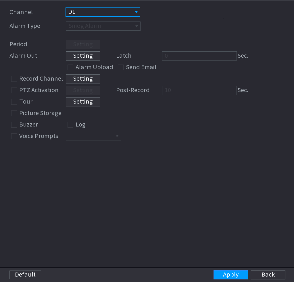
Select channel and alarm type
Select a channel and alarm type, enable the thermal alarm function.
Select the fire mode
Select fire mode and then enable this function (If the alarm type is Fire Alarm). System supports preset mode and zone excluded mode.
- Preset: Select a preset and then enable the function. System generates an alarm once it detect there is a fire.
- Global: System filters the specified high temperature zone. System generates an alarm once the rest zone has fire.
Set parameters
Set parameters. See the table below.
| Parameter | Description |
|---|---|
| Alarm Out | The alarm device (such as lights, sirens, etc.) is connected to the alarm output port. When an alarm occurs, the NVR device transmits the alarm information to the alarm device. |
| Latch | When the alarm ends, the alarm extended for a period of time. The time range is from 0 seconds to 300 seconds. |
| Show Message | Check box to enable a pop-up message in your local host PC. |
| Alarm Upload | Select the check box. When an alarm occurs, the NVR device uploads an alarm signal to the network (including the alarm center). This function is for some series products only. You need to set the alarm center first. For details, see 4.12.9 Alarm Centre. |
| Send Email | Select the check box. When an alarm occurs, the NVR device sends an email to the set mailbox to notify the user. You need to set the email first. For details, see 4.12.6 Email. |
| Record Channel | Select the check box and select the needed recording channel (support multiple choices). When an alarm occurs, the NVR device activates the channel for recording. You need to enable intelligent recording and auto recording first. For details, see 4.1.4.6 Schedule. |
| PTZ Activation | Select the check box and click Setting to select the channel and PTZ action. When an alarm occurs, the NVR device associates the channel to perform the corresponding PTZ action. For example, activate the PTZ in channel one to turn to the preset point X. Tripwire alarm supports to activate PTZ preset point only. You need to set the corresponding PTZ actions first, see 4.4.3 Configuring PTZ Functions. |
| Delay | At the end of the alarm, the recording extends for a period of time. The time range is from 10 seconds to 300 seconds. |
| Tour | Select the check box and select the channel for tour. When an alarm occurs, the local interface of the NVR device displays the selected channel screen. You need to set the time interval and mode for tour first, see 4.16.2 Tour. After the tour is over, the preview interface is restored to the screen split mode before the tour. |
| Log | Select the check box, the NVR device records the alarm information in the log when an alarm occurs. |
| Voice Prompts | Check the box and then select the corresponding audio file from the dropdown list. System plays the audio file when the alarm occurs. Refer to 4.17.1 File Manage to add audio file first. |
| Buzzer | Select the check box to activate the buzzer when an alarm occurs. |
| Record Channel | Select the check box and select the needed recording channel (support multiple choices). When an alarm occurs, the NVR device activates the channel for recording. You need to enable intelligent recording and auto recording first. For details, see 4.1.4.6 Schedule. |
Save
Click Apply.
Abnormality
Open the Abnormality interface
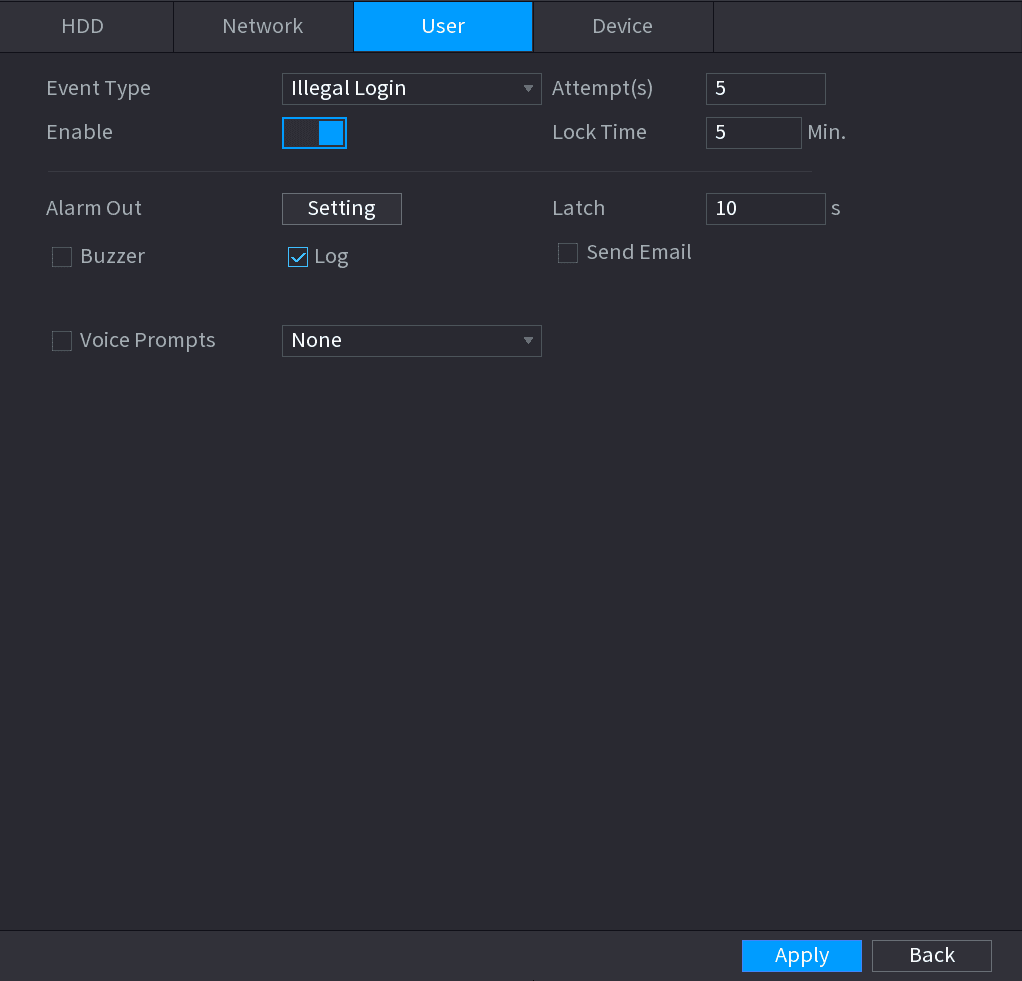
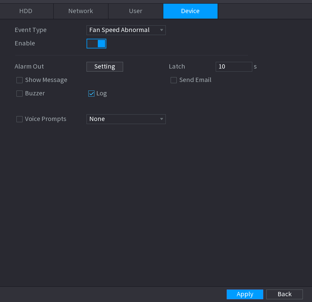
Select Main Menu > ALARM > ABNORMALITY. The Abnormality interface is displayed. See the figures below.
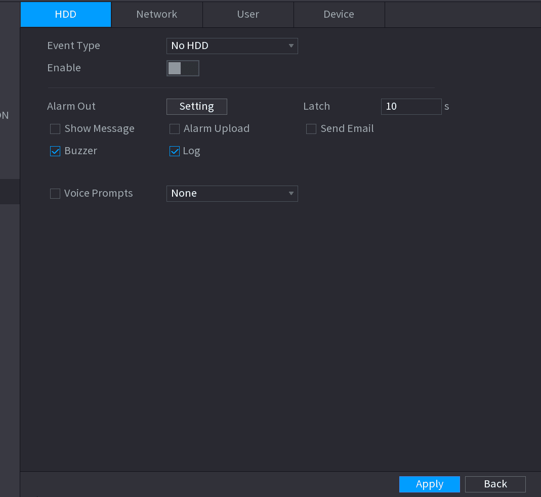
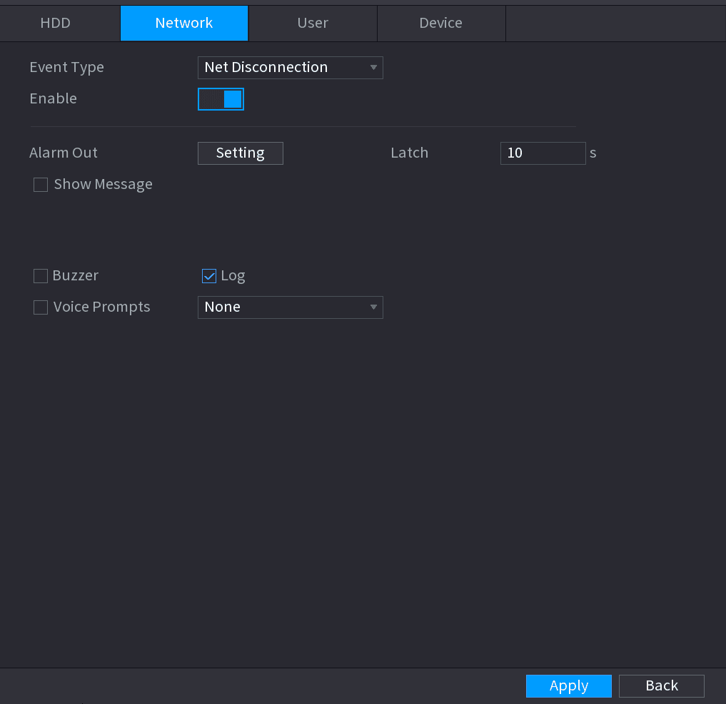
Configure parameters
Configure parameters. See the table below.
| Parameter | Description |
|---|---|
| Event Type | Click the corresponding tab to set different abnormality events. - HDD: Sets process method when there is a HDD event such as HDD error, no HDD, no space. - Network: Sets process method when there is a network event such as disconnection, IP conflict, MAC conflict. - User: Sets process method when there is an Illegal login event. - Device: Sets process method when fan speed is abnormal, or there is a network security event. Different series products support different event types. The actual product shall prevail. |
| Enable | Check the box to enable the function. |
| Less than | System generates an alarm once the HDD space is less than the threshold. For HDD Space type only. |
| Attempts | Set the maximum number of allowable wrong password entries. The account will be locked after your entries exceed the maximum number. For Illegal Login type only. |
| Lock Time | Set how long the account is locked for. The value ranges from 1 minute to 60 minutes. For Illegal Login type only. |
| Alarm Out | The alarm device (such as lights, sirens, etc.) is connected to the alarm output port. When an alarm occurs, the NVR device transmits the alarm information to the alarm device. |
| Latch | When the alarm ends, the alarm extended for a period of time. The time range is from 0 seconds to 300 seconds. |
| Show Message | Check box to enable a pop-up message in your local host PC. |
| Alarm Upload | Select the check box. When an alarm occurs, the NVR device uploads an alarm signal to the network (including the alarm center). This function is for some series products only. You need to set the alarm center first. For details, see 4.12.9 Alarm Centre. |
| Send Email | Select the check box. When an alarm occurs, the NVR device sends an email to the set mailbox to notify the user. You need to set the email first. For details, see 4.12.6 Email. |
| Record Channel | Select the check box and select the needed recording channel (support multiple choices). When an alarm occurs, the NVR device activates the channel for recording. You need to enable intelligent recording and auto recording first. For details, see 4.1.4.6 Schedule. |
AI Database
Configure the AI database on the LTS Sapphire Series NVR — create a face library, add face pictures one by one or in batch for face recognition, and manage vehicle plate black/whitelists.
POS
How to connect the NVR to a POS (Point of Sale) machine to receive, search, and overlay transaction information in the live view and playback screens.