 LTS Connect 帮助中心
System Maintenance
Procedures for storage device maintenance, log search and export, configuration import/export, firmware upgrade, restoring defaults, and system service settings on the Turbo HD DVR GUI 4.0.
Storage Device Maintenance
Configure Disk Clone
Purpose: Select the HDDs to clone to eSATA HDD.
Before you start: Connect an eSATA disk to the device.
Go to HDD Clone
Go to Maintenance > HDD Operation > HDD Clone.
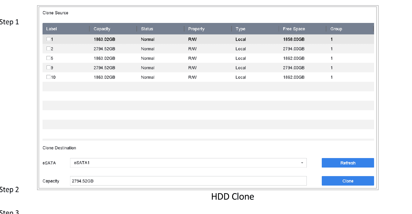
Figure 17-1 HDD Clone
Select source HDDs
Check the HDD to clone. The capacity of selected HDD must match the capacity of clone destination.
Start clone
Click Clone.
Confirm
Click Yes on popup message box to continue clone.
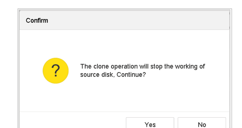
Figure 17-2 Message Box
S.M.A.R.T Detection
Purpose: The device provides HDD detection function including S.M.A.R.T. and Bad Sector Detection technique. The S.M.A.R.T. (Self-Monitoring, Analysis and Reporting Technology) is a monitoring system for HDD to detect and report on various indicators of reliability in the hopes of anticipating failures.
Open S.M.A.R.T interface
Go to Maintenance > HDD Operation > S.M.A.R.T.
Select HDD
Select the HDD to view its S.M.A.R.T information list.
Select self-test type
Select the self-test types as Short Test, Expanded Test or Conveyance Test.
Run self-test
Click Self-Test to start the S.M.A.R.T. HDD self-evaluation.
The related information of the S.M.A.R.T. is shown on the interface. You can check the HDD status.
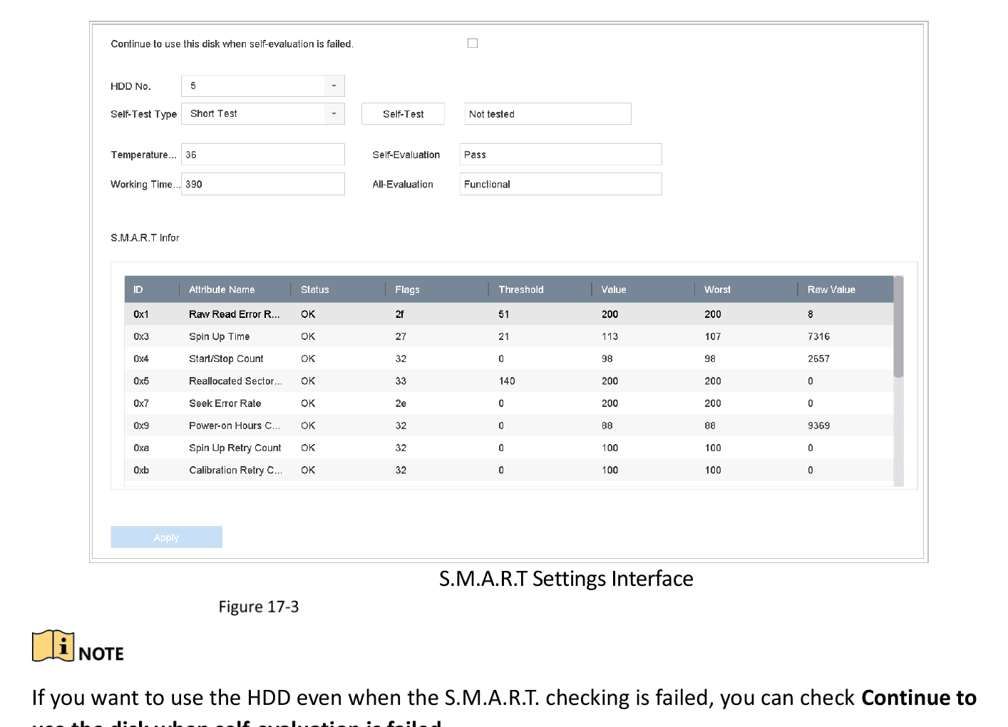
Figure 17-3 S.M.A.R.T Settings Interface
If you want to use the HDD even when the S.M.A.R.T. checking is failed, you can check Continue to use the disk when self-evaluation is failed.
Bad Sector Detection
Open Bad Sector Detection
Go to Maintenance > HDD Operation > Bad Sector Detection.
Select HDD
Select the HDD No. in the dropdown list you want to configure.
Select detection type
Select All Detection or Key Area Detection as the detection type.
Start detection
Click Self-Test to start the detection.
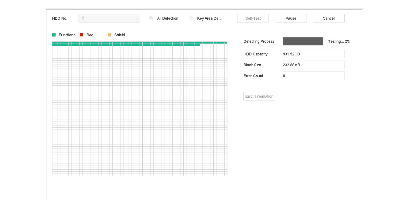
Figure 17-4 Bad Sector Detection
- You can also pause/resume or cancel the detection.
- After testing completed, click Error information to see the detailed damage information.
HDD Health Detection
Purpose: You can view the health status of Seagate HDD that generated after October 1th, 2017 and provides capacity ranges from 4 TB to 8 TB. The function helps you to troubleshoot HDD problems. Compared with S.M.A.R.T function, health detection shows HDD status with more details.
Open Health Detection
Go to Maintenance > HDD Operation > Health Detection.
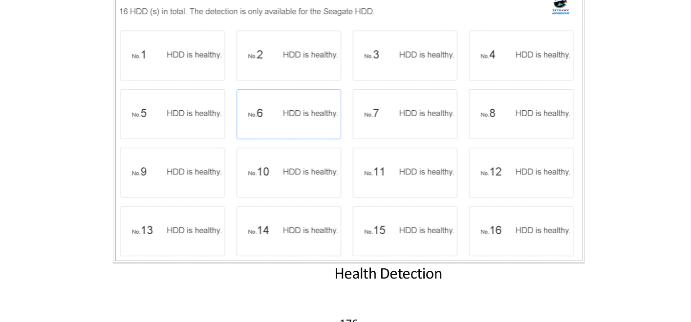
Figure 17-5 Health Detection
View HDD details
Click a HDD to view details.
Search and Export Log Files
Purpose: The operation, alarm, exception and information of the device can be stored in log files, which can be viewed and exported at any time.
Search the Log Files
Open Log Information
Go to Maintenance > Log Information.
Set search conditions
Set the log search conditions.
Search
Click Search to start search log files.
The matched log files will be displayed in the list shown below.

Figure 17-6 Log Search Results
Up to 2000 log files can be displayed each time.
Related Operation:
- Click or double click a log entry to view its detailed information.
- Click the play icon to view the related video file.
Export the Log Files
Before You Start: Connect a storage device to your device.
Search log files
Search the log files. Refer to Search the Log Files.
Select and export
Select the log files you want to export, and click Export.
Or you can click Export ALL on the Log Search interface to export all the system logs to the storage device.
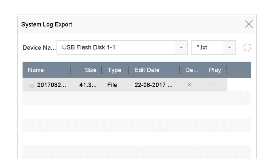
Figure 17-7 Export Log Files
Select storage device
Select the storage device from the dropdown list of Device Name.
Select format
Select the format of the log files to be exported. Up to 15 formats are selectable.
Confirm export
Click Export to export the log files to the selected storage device.
Related Operation:
- Click New Folder to create new folder in the storage device.
- Click Format to format the storage device before log export.
Import/Export IP Camera Configuration Files
Purpose: The information of added IP camera can be generated into an excel file and exported to the local device for backup, including the IP address, manage port, password of admin, etc. And the exported file can be edited on your PC, like adding or deleting the content, and copy the setting to other devices by importing the excel file to it.
Before You Start: Connect a storage device to your device. For importing the configuration file, the storage device must be with the file.
Open IP Camera Import/Export
Go to Camera > IP Camera Import/Export.
Open the tab
Click the IP Camera Import/Export tab, and the content of detected plugged external device appears.
Export or import
Export or import the IP camera configuration files.
- Click Export to export configuration files to the selected local backup device.
- To import a configuration file, select the file from the selected backup device and click the Import button.
After the importing process is completed, you must reboot the device to activate the settings.
Import/Export Device Configuration Files
Purpose: The configuration files of the device can be exported to local device for backup; and the configuration files of one device can be imported to multiple devices if they are to be configured with the same parameters.
Before You Start: Connect a storage device to your device. For importing the configuration file, the storage device must be with the file.
Open Import/Export
Go to Maintenance > Import/Export.
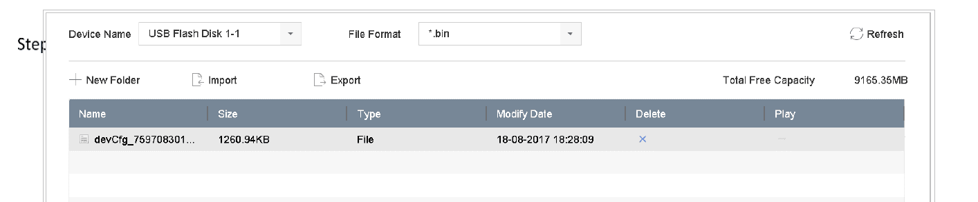
Figure 17-8 Import/Export Config File
Export or import
Export or import the device configuration files.
- Click Export to export configuration files to the selected local backup device.
- To import a configuration file, select the file from the selected backup device and click Import.
After having finished the import of configuration files, the device will reboot automatically.
Upgrade System
Purpose: The firmware on your device can be upgraded by local backup device or remote FTP server.
Upgrade by Local Backup Device
Before You Start: Connect your device with a local storage device with update firmware file.
Open Local Upgrade
Go to Maintenance > Upgrade > Local Upgrade to enter the local upgrade interface.
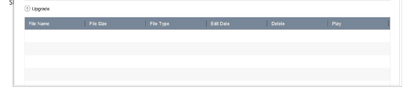
Figure 17-9 Local Upgrade Interface
Select update file
Select the update file from the storage device.
Start upgrade
Click Upgrade to start upgrading.
Reboot
After the upgrading is complete, the device will reboot automatically to activate the new firmware.
Upgrade by FTP
Before you start: Ensure the network connection of the PC (running FTP server) and the device is valid and correct. Run the FTP server on the PC and copy the firmware into the corresponding directory of your PC.
Open FTP Upgrade
Go to Maintenance > Upgrade > FTP to enter the local upgrade interface.
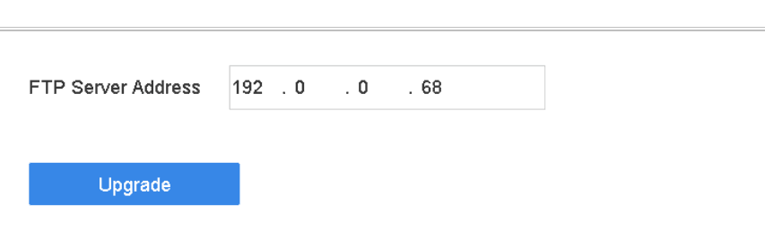
Figure 17-10 FTP Upgrade Interface
Enter FTP address
Enter IP address of FTP Server Address.
Start upgrade
Click Upgrade to start upgrading.
Reboot
After the upgrading is complete, reboot the device to activate the new firmware.
Upgrade by Online Downloading
Before You Start: Connect your device to Hik-Connect and put the update firmware file in Hik-Connect.
Open Online Upgrade
Go to Maintenance > Upgrade > Online Upgrade.
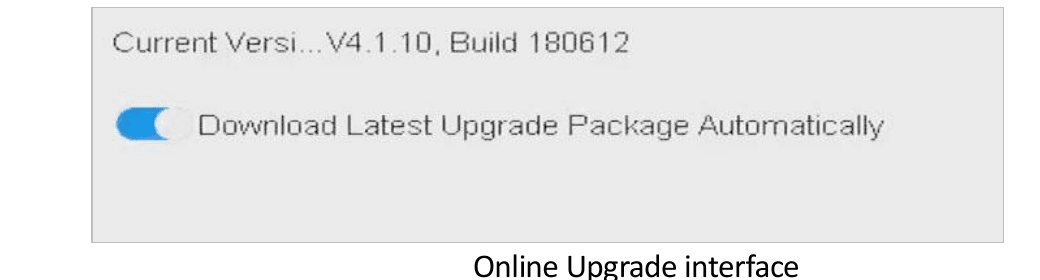
Figure 17-11 Online Upgrade Interface
Enable auto download
Turn on Download Latest Upgrade Package Automatically.
Upgrade Camera
Purpose: You can upgrade multiple connected analog cameras supporting Turbo HD or AHD signal simultaneously with DVR.
Open Camera Upgrade
Go to Maintenance > Upgrade > Camera Upgrade.
Select cameras
Check the checkbox(es) of the analog camera(s) for upgrading.
The analog camera must support Turbo HD or AHD signal.
Select update file
Select the update file from the backup device.
Start upgrade
Click Upgrade to start upgrading.
Restore Default Settings
Open Default settings
Go to Maintenance > Default.
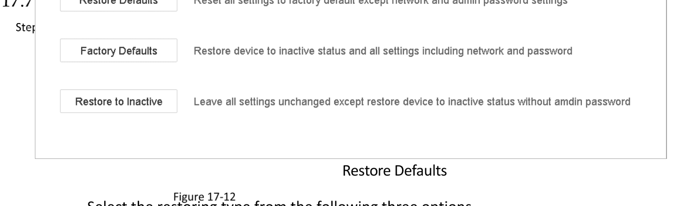
Figure 17-12 Restore Defaults
Select restore type
Select the restoring type from the following three options.
| Option | Description |
|---|---|
| Restore Defaults | Restore all parameters, except the network (including IP address, subnet mask, gateway, MTU, NIC working mode, default route, server port, etc.) and user account parameters, to the factory default settings. |
| Factory Defaults | Restore all parameters to the factory default settings. |
| Restore to Inactive | Restore the device to the inactive status. |
The device will reboot automatically after restoring to the default settings.
System Service
Network Security Settings
Disable SADP Services
Purpose: You can disable SADP service to enhance the access security, e.g., when you are in the untrusted network environment.
Open System Service
Go to System > System Service > System Service.
Disable SADP
Uncheck Enable SADP to disable the service.
HTTP
You can choose to disable the HTTP, or set the HTTP authentication when it is enabled as demand to enhance the access security.
By default, the HTTP service is enabled.
Set HTTP Authentication
Purpose: If you need to enable the HTTP service, you can set the HTTP authentication to enhance the access security.
Open System Service
Go to System > System Service > System Service.

Figure 17-13 HTTP Authentication
Enable HTTP
Check the Enable HTTP to enable the HTTP service.
Set authentication type
Select the digest as the HTTP Authentication in the drop-down list.
Save
Click Save to save the settings.
Two authentication types are selectable: digest and digest/basic. For security reasons, it is recommended to select digest as the authentication type.
Disable HTTP
Purpose: The admin user account can disable the HTTP service from the GUI or the web browser. After the HTTP is disabled, all its related services, including the ISAPI, Onvif and Gennetc, will terminate as well.
Open System Service
Go to System > System Service > System Service.
Disable HTTP
Uncheck the Enable HTTP to disable the HTTP service.
RTSP Authentication
Purpose: You can specifically secure the stream data of live view by setting the RTSP authentication.
Open System Service
Go to System > System Service > System Service.

Figure 17-14 RTSP Authentication
Select authentication type
Select the authentication type.
Save
Click Save to save the settings.
Two authentication types are selectable: digest and digest/basic. If you select digest, as the RTSP authentication, only the request with digest authentication can access the video stream by the RTSP protocol via the IP address. For security reasons, it is recommended to select digest as the authentication type.
Managing ONVIF User Accounts
Purpose: For the third-party camera connection to the device via ONVIF, you can enable ONVIF function and manage the user accounts.
Open ONVIF settings
Go to System > System Service > ONVIF.
Enable ONVIF
Check Enable ONVIF to enable the ONVIF access management.
Add user
Click Add to enter the Add User interface.
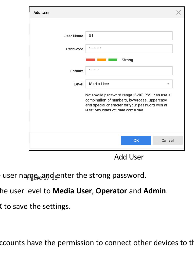
Figure 17-15 Add User
Configure user
Edit the user name, and enter the strong password.
Set user level
Select the user level to Media User, Operator and Admin.
Save
Click OK to save the settings.
Result: The added user accounts have the permission to connect other devices to the device via ONVIF protocol.
ONVIF protocol is disabled by default.
Managing IP Camera Activation
When you activate the device for the first-time access, you can set the activation password for the IP camera(s) as well. Refer to Activate the Device. And you can also manage the password to enhance the security.
Open IP Camera Activation
Go to System > System Service > IP Camera Activation.
Enable change password
Check the Change Password to enable the permission.
Enter admin password
Enter the admin password of the device to obtain the permission.
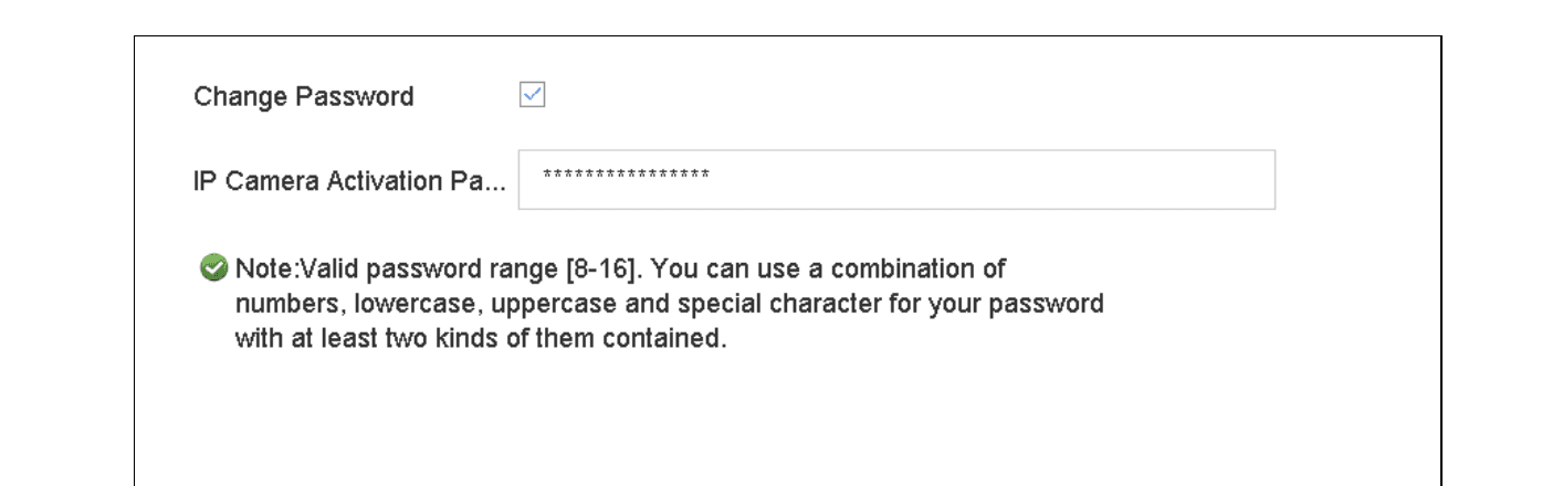
Figure 17-16 Change IP Camera Activation Password
Enter new password
In the text filed of the IP Camera Activation Password, enter the new strong password for the cameras.
Apply
Click Apply to have the following pop-up attention box.
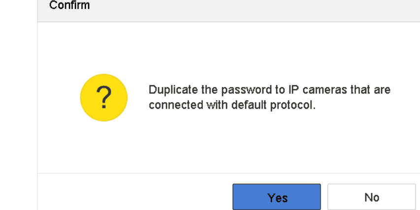
Figure 17-17 Attention
Confirm
Click Yes to duplicate the current password to the IP cameras which are connected with the default protocol.
Storage
Configure storage devices, HDD groups, quota mode, recording schedules, picture capture, holiday recording, redundant recording, and 1080p Lite mode on the Turbo HD DVR GUI 4.0.
VCA Event Alarm
Configure VCA smart event alarms on the Turbo HD DVR GUI 4.0, including human body, face, vehicle, line crossing, intrusion, region entrance/exiting, unattended baggage, object removal, audio exception, sudden scene change, defocus, and PIR detection.