 מרכז העזרה של LTS Connect
Event and Alarm Settings
Configure arming schedules, alarm linkage actions, motion detection, video loss, video tampering, sensor alarm inputs and outputs, exception handling, and manual alarm control on the Turbo HD DVR GUI 4.0.
Configure Arming Schedule
Select the Arming Schedule tab
Select the Arming Schedule tab.
Set time segments
Choose one day of a week and set the time segment. Up to eight time periods can be set within each day.
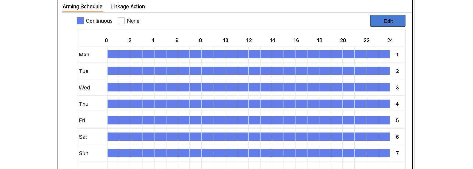
Figure 11-1 Set Arming Schedule
Time periods shall not be repeated or overlapped.
Save
Click Apply to save the settings.
Configure Alarm Linkage Actions
Purpose: Alarm linkage actions will be activated when an alarm or exception occurs, including Event Hint Display, Full Screen Monitoring, Audible Warning (buzzer), Notify Surveillance Center, Trigger Alarm Output and Send Email.
Configure Auto-switch Full Screen Monitoring
When an alarm is triggered, the local monitor displays in full screen the video image from the alarming channel configured for full screen monitoring. And when the alarm is triggered simultaneously in several channels, you must configure the auto-switch dwell time.
Set event output and dwell time
Go to System > View > General.
Set the event output and dwell time.
- Event Output: Select the output to show event video.
- Full Screen Monitoring Dwell Time: Set the time in seconds to show alarm event screen. If alarms are triggered simultaneously in several channels, their full-screen images will be switched at an interval of 10 seconds (default dwell time).
Select Full Screen Monitoring linkage
Go to the Linkage Action interface of the alarm detection (e.g., motion detection, video tampering, face detection, etc.).
Select the Full Screen Monitoring alarm linkage action.
Select channels
Select the channel(s) in Trigger Channel settings you want to make full screen monitoring.
Auto-switch will terminate once the alarm stops and back to the live view interface.
Configure Audio Warning
The audio warning enables the system to trigger an audible beep when an alarm is detected.
Enable audio output
Go to System > View > General.
Enable the audio output and set the volume.
Select Audio Warning linkage
Go to the Linkage Action interface of the alarm detection (e.g., motion detection, video tampering, face detection, etc.).
Select the Audio Warning alarm linkage action.
Notify Surveillance Center
The device can send an exception or alarm signal to the remote alarm host when an event occurs. The alarm host refers to the PC installed with client software (e.g., iVMS-4200, iVMS-5200).
Set alarm host
Go to System > Network > Advanced > More Settings.
Set the alarm host IP and alarm host port.
Select Notify Surveillance Center linkage
Go to the Linkage Action interface of the alarm detection (e.g., motion detection, video tampering, face detection, etc.).
Select Notify Surveillance Center.
Configure Email Linkage
The system can send an email with alarm information to a user or users when an alarm is detected.
Please refer to Chapter 16.7 Configure Email for details of Email configuration.
Configure Email settings
Go to System > Network > Advanced.
Configure the Email settings.
Select Send Email linkage
Go to the Linkage Action interface of the alarm detection (e.g., motion detection, video tampering, face detection, etc.).
Select the Send Email alarm linkage action.
Trigger Alarm Output
The alarm output can be triggered by the alarm input, motion detection, video tampering detection, face detection, line crossing detection, and all other events.
Select alarm outputs to trigger
Go to the Linkage Action interface of the alarm input or event detection (e.g., motion detection, face detection, line crossing detection, intrusion detection, etc.).
Click the Trigger Alarm Output tab.
Select the alarm output(s) to trigger.
Configure alarm output settings
Go to System > Event > Normal Event > Alarm Output.
Select an alarm output item from the list.
Refer to Configure Alarm Output for the alarm output settings.
Configure PTZ Linkage
The system can trigger the PTZ actions (e.g., call preset/patrol/pattern) when the alarm event, or VCA detection events occur.
Make sure the PTZ or speed dome connected supports PTZ linkage.
Select PTZ Linkage
Go to the Linkage Action interface of the alarm input or VCA detection (e.g., face detection, line crossing detection, intrusion detection, etc.).
Select PTZ Linkage.
Select camera and action
Select the camera to perform the PTZ actions.
Select the preset/patrol/pattern No. to call when the alarm events occur.
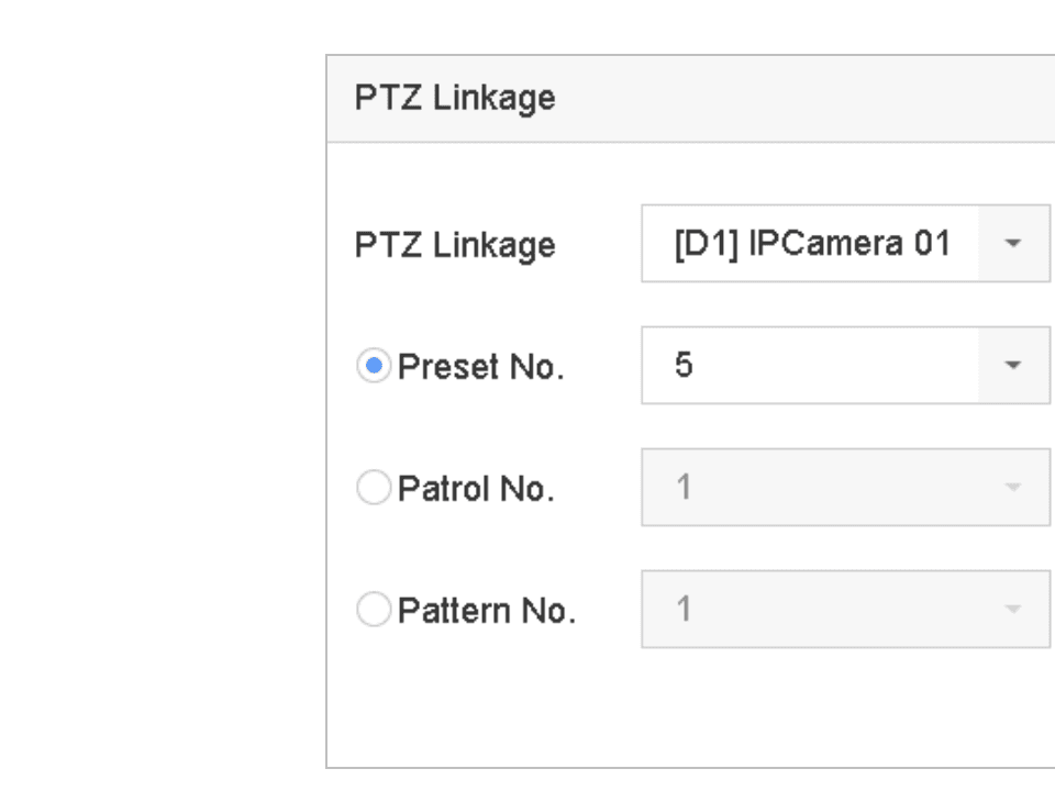
Figure 11-2 PTZ Linkage
You can set one PTZ type only for the linkage action each time.
Configure Motion Detection Alarm
The motion detection enables the device to detect the moving objects in the monitoring area and trigger the alarm.
Open Motion Detection settings
Go to System > Event > Normal Event > Motion Detection.
Select camera and enable
Select the camera to configure the motion detection.
Check Enable.
Set detection area
Set the motion detection area.
- Full screen: click to set the full-screen motion detection for the image.
- Customized area: use the mouse to click and drag on the preview screen to draw the customized motion detection area(s).
You can click Clear to clear the current motion detection area settings and draw again.
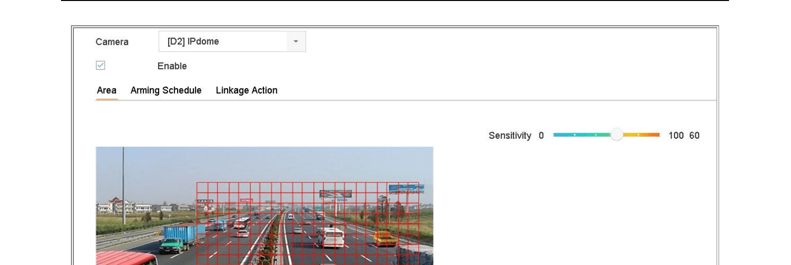
Figure 11-3 Set Motion Detection
Set sensitivity
Set sensitivity (0–100). The sensitivity allows you to calibrate how readily movement triggers the alarm. The higher value results in the more readily to trigger the motion detection.
Configure arming schedule
Set the arming schedule. Refer to Configure Arming Schedule.
Configure linkage actions
Set the linkage actions. Refer to Configure Alarm Linkage Actions.
Configure Video Loss Alarm
Purpose: The video loss detection enables to detect video loss of a channel and take alarm response action(s).
Open Video Loss settings
Go to System > Event > Normal Event > Video Loss.
Select camera and enable
Select the camera to configure the video loss detection.
Check Enable.
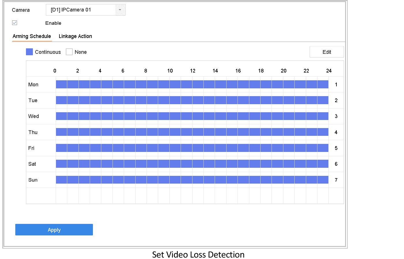
Figure 11-4 Set Video Loss Detection
Configure arming schedule
Set the arming schedule. Refer to Configure Arming Schedule.
Configure linkage actions
Set the linkage actions. Refer to Configure Alarm Linkage Actions.
Configure Video Tampering Alarm
Purpose: The video tampering detection enables to trigger alarm when the camera lens is covered and take alarm response action(s).
Open Video Tampering settings
Go to System > Event > Normal Event > Video Tampering.
Select camera and enable
Select the camera to configure the video tampering detection.
Check Enable.
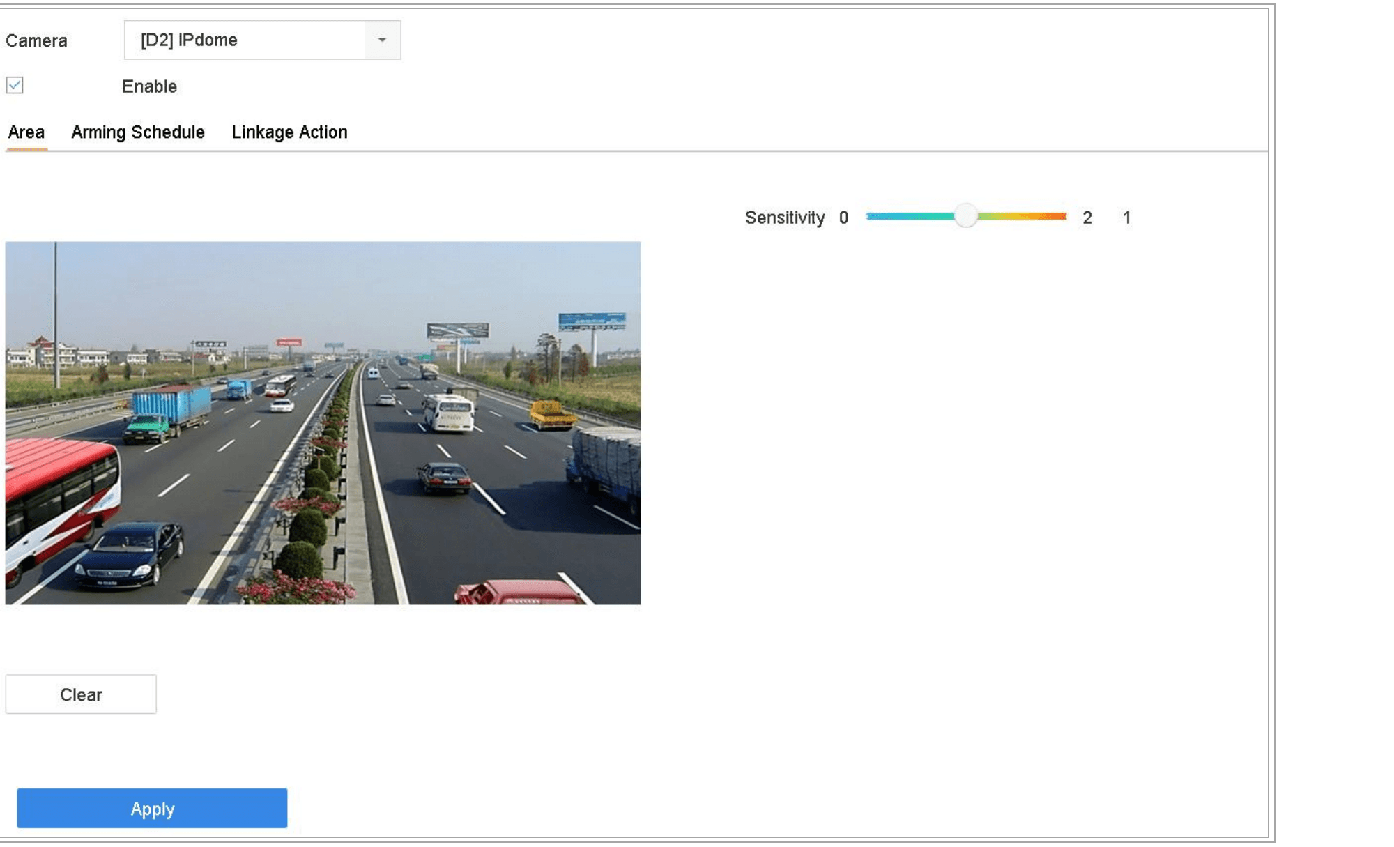
Figure 11-5 Set Video Tampering Setting
Set tampering area
Set the video tampering area. Use the mouse to click and drag on the preview screen to draw the customized video tampering area.
You can click Clear to clear the current area settings and draw again.
Set sensitivity
Set sensitivity level (0–2). 3 levels are available. The sensitivity allows you to calibrate how readily movement triggers the alarm. The higher value results in the more readily to trigger the video tampering detection.
Configure arming schedule
Set the arming schedule. Refer to Configure Arming Schedule.
Configure linkage actions
Set the linkage actions. Refer to Configure Alarm Linkage Actions.
Configure Sensor Alarms
Purpose: Set the handling action of an external sensor alarm.
Configure Alarm Input
Open Alarm Input
Go to System > Event > Normal Event > Alarm Input.
Select an alarm input item from the list and click  .
.
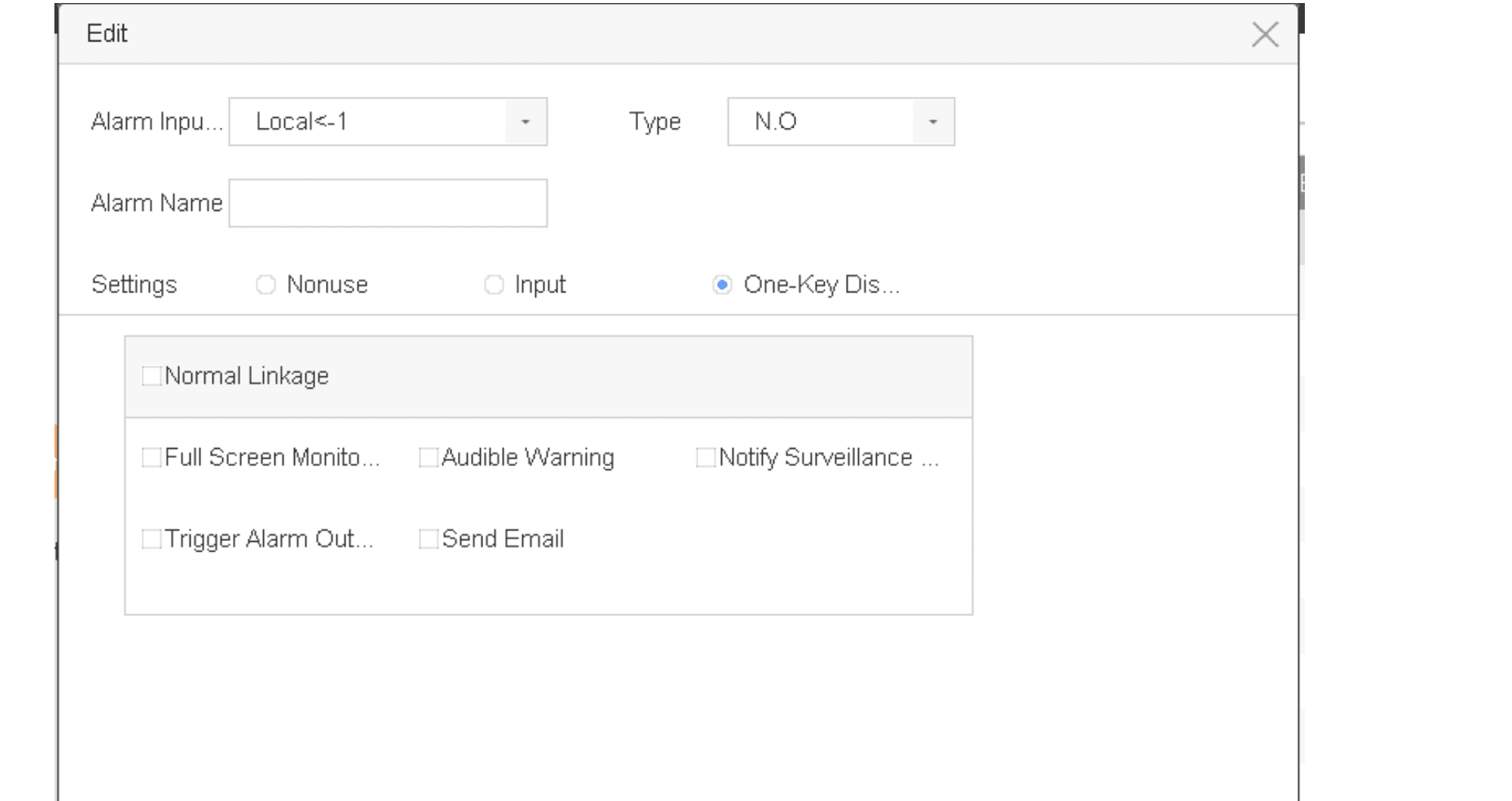
Figure 11-6 Alarm Input
Select alarm input type
Select the alarm input type to N.C or N.O.
Edit alarm name
Edit Alarm Name.
Select Input
Select Input.
Configure arming schedule
Set the arming schedule. Refer to Configure Arming Schedule.
Configure linkage actions
Set the linkage actions. Refer to Configure Alarm Linkage Actions.
Apply
Click Apply and follow the message box to reboot device to take effect the settings.
Configure One-Key Disarming
The one-key disarming enables the device to disarm the alarm input 1 by one-key operation.
Open Alarm Input 1
Go to System > Event > Normal Event > Alarm Input.
Select the alarm input1 item from the list and click .
Configure type and name
Select the alarm input type to N.C or N.O.
Edit the alarm name.
Enable One-Key Disarming
Check the radio button of Enable One-Key Disarming.
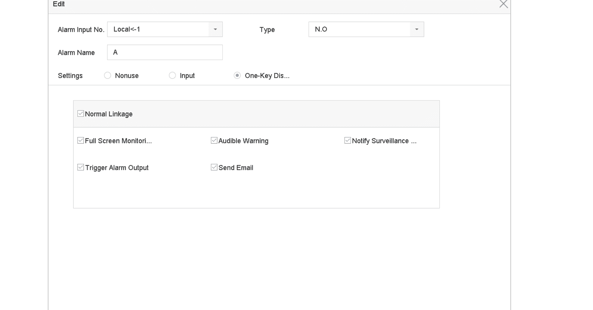
Figure 11-7 One-Key Alarm Disarming
Select linkage actions to disarm
Select the alarm linkage action(s) you want to disarm for the local alarm input1.
When the alarm input 1 (Local<-1) is enabled with one-key disarming, the other alarm input settings are not configurable.
Apply
Click Apply to save the settings.
Configure Alarm Output
Trigger an alarm output when an alarm is triggered.
Open Alarm Output
Go to System > Event > Normal Event > Alarm Output.
Select an alarm output item from the list and click .
Edit alarm name
Edit Alarm Name.
Select Dwell Time
Select Dwell Time (the alarm duration) from 5s to 600s, or Manually Clear.
Manually Clear: You should manually clear the alarm when the alarm occurs. Refer to Trigger or Clear Alarm Output Manually for detailed instructions.
Configure arming schedule
Set the arming schedule. Refer to Configure Arming Schedule.
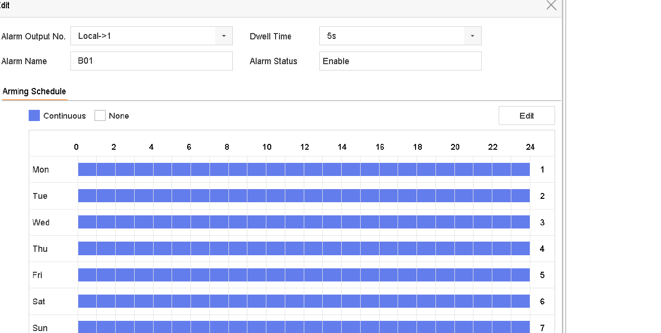
Figure 11-8 Alarm Output
Copy and Apply
(Optional) You can click Copy to copy the same settings to other alarm output(s).
Click Apply.
Configure Exceptions Alarm
The exception events can be configured to take the event hint in the live view window, trigger alarm output and linkage actions.
Open Exception settings
Go to System > Event > Normal Event > Exception.
Enable event hint
(Optional) Enable the event hint if you want to display the event hint in the live view window.
- Check Enable Event Hint.
- Click
 to select the exception type(s) to take the event hint.
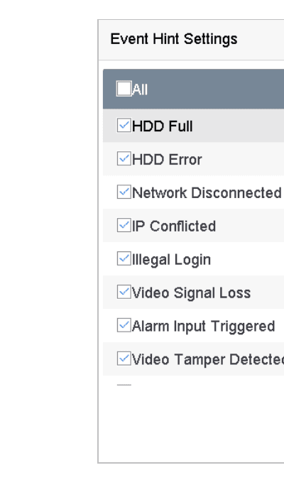
Figure 11-9 Event Hint Settings
Select exception type and configure linkage
Select the exception type from the drop-down list to set the linkage actions.
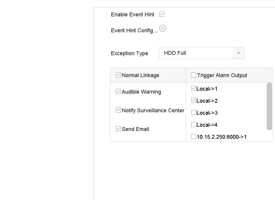
Figure 11-10 Exceptions Handling
Set the normal linkage and alarm output triggering. Refer to Configure Alarm Linkage Actions.
Trigger or Clear Alarm Output Manually
Purpose: Sensor alarm can be triggered or cleared manually. When Manually Clear is selected for the dwell time of an alarm output, the alarm can be cleared only by clicking Clear.
Open Alarm Output
Go to System > Event > Normal Event > Alarm Output.
Trigger or clear
Select the alarm output you want to trigger or clear and click .
Click Trigger/Clear to trigger or clear an alarm output.
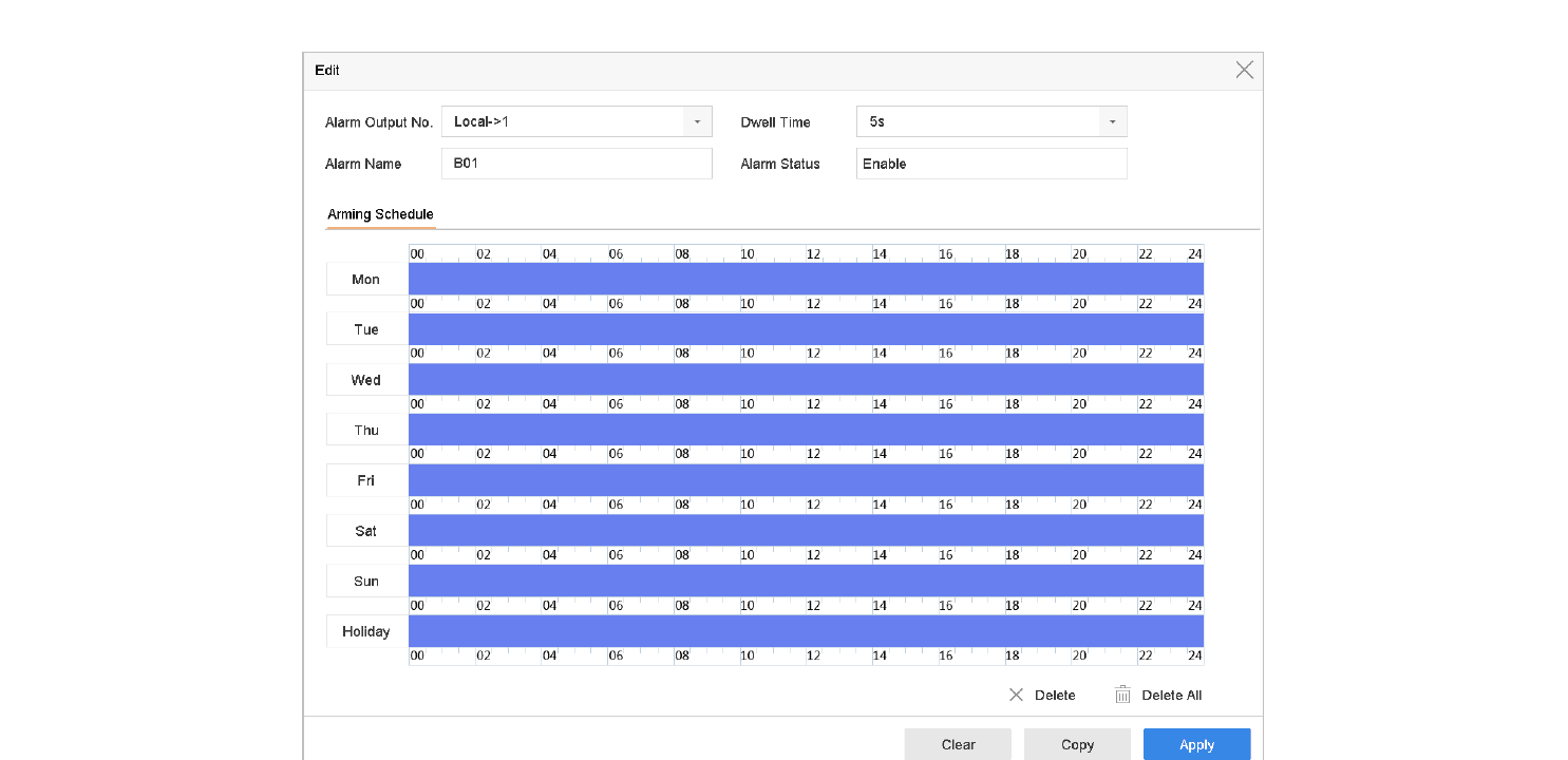
Figure 11-11 Alarm Output
Playback
Comprehensive guide to playing back recorded video on the Turbo HD DVR GUI 4.0, covering instant playback, normal playback, smart search, custom search, tag files, event files, sub-periods, log files, external files, and playback operations.
POS Configuration
Connect the DVR to a POS machine or server to overlay transaction text on live view and playback, and configure POS event alarms.