 مرکز راهنمایی LTS Connect
Live View
Use the Sapphire NVR Live View to preview channel video, operate the navigation bar and shortcut menu, perform instant replay, digital zoom, fisheye de-warp, temperature test, and AI preview.
Live View
After you logged in, the system goes to multiple-channel live view mode by default. You can view the monitor video of each channel.
The displayed window amount may vary. The actual product shall prevail.
Preview
On Preview interface, you can view the monitor video of each channel. The corresponding channel displays date, time, and channel name after you overlay the corresponding information. Refer to the following table for detailed information. See Table 4-16.
Table 4-16
| SN | Icon | Description |
|---|---|---|
| 1 | Recording icon | When current channel is recording, system displays this icon. |
| 2 | Motion detection icon | When motion detection alarm occurs, system displays this icon. |
| 3 | Video loss icon | When video loss alarm occurs, system displays this icon. |
| 4 | Monitor lock icon | When current channel is in monitor lock status, system displays this icon. |
| 5 | Remote connection icon | When the device connects to the network camera remotely, system displays this icon. This function is for some series products only. |
Navigation bar
You can quickly perform operation through the icon on the navigation bar.
- Different series products may display different navigation bar icons. Refer to the actual product for detailed information.
- Select Main Menu > SYSTEM > GENERAL > General to enable navigation bar function and then click Apply; otherwise you cannot see the following interface.
Display the navigation bar
On the preview interface, left click mouse. You can see navigation bar. See Figure 4-62. Refer to Table 4-17 to view detailed information.

Table 4-17
| Icon | Function |
|---|---|
| Main Menu | Open Main Menu. |
| Expand/condense | Expand or condense the navigation bar. |
| View layout | Select view layout. |
| Previous screen | Go to the previous screen. |
| Next screen | Go to the next screen. |
| Tour | Enable tour function. The icon switches to the tour-on icon. |
| Stop tour | Close the tour or the triggered tour operation has cancelled, device restores the previous preview video. |
| PTZ | Open the PTZ control panel. For details, see 4.4.2 PTZ Control. |
| Color | Open the Color Setting interface. For details, see 4.4.2 PTZ Control. This function is supported only in single-channel layout. |
| Record search | Open the record search interface. For detail, see 4.6.2 Search Interface. |
| Broadcast | Open the Broadcast interface. For detail, see 4.17.3 Broadcast. |
| Event | Open the EVENT interface to view the device alarm status. For details, see 4.8.2 Alarm Status. |
| Channel Info | Open the CHANNEL INFO interface to display the information of each channel. For details, see 4.3.2.1 Channel Info. |
| Camera Registration | Open the CAMERA REGISTRATION interface. For details, see 4.1.4.4 Registration. |
| Network | Open the NETWORK interface. For details, see 4.12 Network. |
| HDD Manager | Open the HDD MANAGER interface. For details, see 4.13.3 HDD. |
| USB Manager | Open the USB MANAGER interface. For details about USB operations, see 4.3.2.2 USB Manager. |
Channel Info
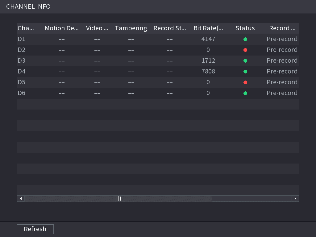
After the remote device registered to the corresponding channel, you can view its status such as alarm status, record status, connection status, record mode, etc.
- Alarm status: It includes motion detection alarm, video loss alarm, tampering alarm.
- Record status: System is recording or not.
- Bit Rate: System displays bit rate information.
- Status: current channel connection status.
Click the Channel Info button, system goes to the channel information setup interface. You can view information of the corresponding channel. See Figure 4-63.
USB Manager
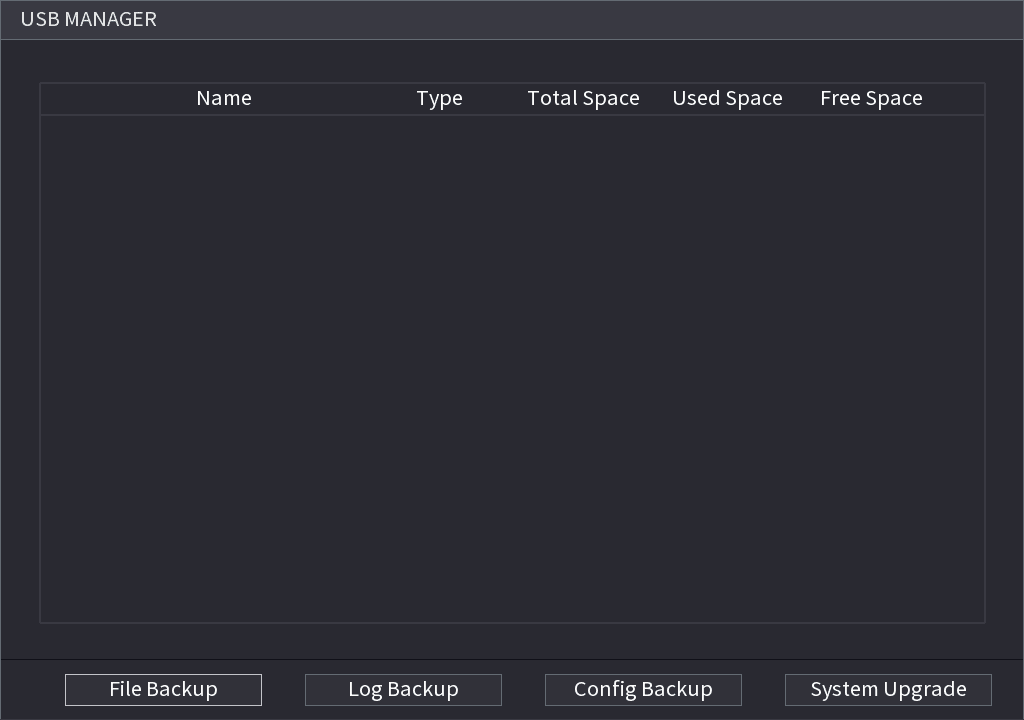
After connecting the USB device, you can copy log, config file to USB device or update NVR system.
Click the USB Manager button, system goes to HDD Manager interface. You can view and manage HDD information. See Figure 4-64.
Here you can view USB information, backup file, and update system. Refer to 4.11 File Backup, 4.10.1 Log, 4.10.4.2 IMP/EXP, 4.10.4.4 System Update for detailed information.
Preview Control Interface
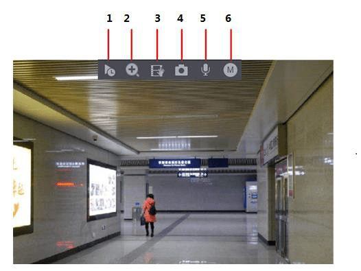
Move your mouse to the top center of the video of current channel; you can see system pops up the preview control interface. See Figure 4-65. If your mouse stays in this area for more than 6 seconds and has no operation, the control bar automatically hides.
Slight difference may be found on the user interface.
Instant Replay
You can playback the previous 5-60 minutes record of current channel.
Click the instant replay button to go to the instant replay interface. See Figure 4-66.
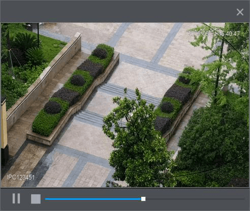
Instant replay is to playback the previous 5 minutes to 60 minutes record of current channel.
- Move the slider to choose the time you want to start playing.
- Play, pause and close playback.
- The information such as channel name and recording status icon are shielded during instant playback and will not display until exited.
- During playback, screen split layout switch is not allowed.
- Tour high higher priority than the instant playback. The instant playback function is null when tour function is in process and the preview control interface auto hides either. The function becomes valid again after tour is complete.
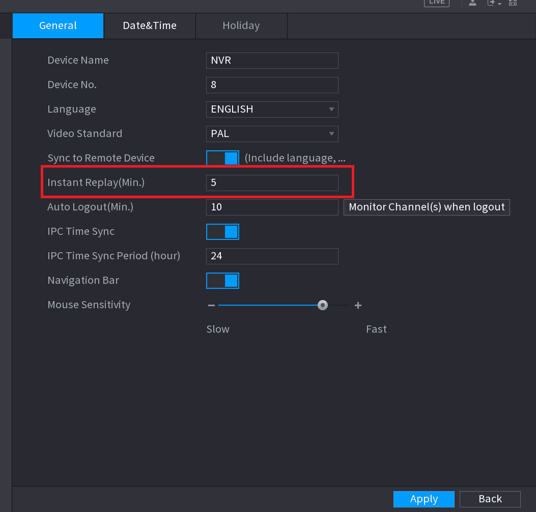
Go to the Main Menu > SYSTEM > GENERAL > General to set Instant Replay time. See Figure 4-67. System may pop up a dialogue box if there is no such record in current channel.
Digital zoom
You can zoom in specified zone of current channel so that you can view the details. It supports zoom in function of multiple-channel. It includes the following two ways:
- Click the zoom icon, the icon switches to the active state. Hold down the left mouse button to select the area you want to enlarge. The area is enlarged after the left mouse button is released.
- Point to the center that you want to enlarge, rotate the wheel button to enlarge the area.
For some models, when the image is enlarged in the first way described previously, the selected area is zoomed proportionally according to the window.
The digital zoom interface is shown as in Figure 4-68. When the image is in the enlarged status, you can drag the image toward any direction to view the other enlarged areas. Right click mouse to cancel zoom and go back to the original interface.
Instant backup
You can record the video of any channel and save the clip into a USB storage device.
By clicking the instant backup button, the recording is started. To stop recording, click this icon again. The clip is automatically saved into the connected USB storage device.
You can record the video of any channel and save the clip into a USB storage device.
Manual Snapshot
You can take one to five snapshots of the video and save into a USB storage device.
By clicking the snapshot button, you can take snapshots. The snapshots are automatically saved into the connected USB storage device. You can view the snapshots on your PC.
To change the quantity of snapshots, select Main Menu > CAMERA > ENCODE > Snapshot, in the Manual Snap list, select the snapshot quantity.
Bidirectional talk
You can perform the voice interaction between the Device and the remote device to improve efficiency of emergency.
Start bidirectional talk
Click the bidirectional talk button to start bidirectional talk function. The icon now is shown as the active state. Now the rest bidirectional talk buttons of digital channel becomes null too.
Cancel bidirectional talk
Click the bidirectional talk button again, you can cancel bidirectional talk.
Switch bit streams
Via this function, you can switch the channel main stream/sub stream according to current network bandwidth.
- M: Main stream. Its bit streams are big and definition is high. It occupies large network bandwidth suitable for video wall surveillance, storage and etc.
- S: Sub stream. Its definition is low but occupies small network bandwidth. It is suitable for general surveillance, remote connection and etc.
Click the bit stream button to switch the bit stream type of the main stream and sub stream.
- M: Main stream.
- S: Sub stream. Some series products support two sub streams (S1, S2). Refer to 4.2.5.1 Encode for detailed information.
Right-Click Menu
By right-clicking the menu, you can quickly access the corresponding functional interface and perform relevant operations, including entering the main menu, searching records and selecting screen split mode.
Right-click on the preview interface and the right-click menu is displayed. See Figure 4-69. Refer to Table 4-18 for detailed information.
The right-click menu is different for different models. The actual interface shall prevail.
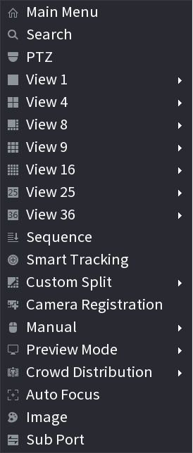
Table 4-18
| Function | Description |
|---|---|
| Main Menu | Open Main Menu interface. |
| Search | Open the PLAYBACK interface where you can search and play back record files. For details, see 4.6 Playback and Search. |
| PTZ | Open the PTZ interface. For details, see 4.4 PTZ. |
| View 1/4/8/9/16/25/36 | Configure the live view screen as a single-channel layout or multi-channel layout. |
| Sequence (View Layout) | Set customized screen split mode and channels. For details, see 4.3.4 Sequence. |
| Previous Screen / Next Screen | Click Previous Screen to go to the previous screen. For example, if you are using 4-split mode, the first screen is displaying the channel 1-4, click Next screen, you can view channel 5-8. |
| Camera Registration | Open the CAMERA REGISTRATION interface. For details, see 4.1.4.4 Registration. |
| Manual | Select Record, you can configure the recording mode as Auto or Manual, or stop the recording. You can also enable or disable snapshot function. Select Alarm Out, you can configure alarm output settings. |
| Preview Mode | There are two modes: regular/AI mode. |
| Crowd Distribution | Select enable/disable to start/stop crowd distribution function. |
| Auto focus | Click to realize auto focus function. Make sure the connected camera supports auto focus function. |
| Image | Click to modify the camera properties. For details, see 4.2.4 Image. |
| Sub Port | Click Sub Port, you can go to control the sub screen. |
Sequence
You can set customized view layout.
The preview layout restores default channel layout after Default operation.
Open the Sequence interface
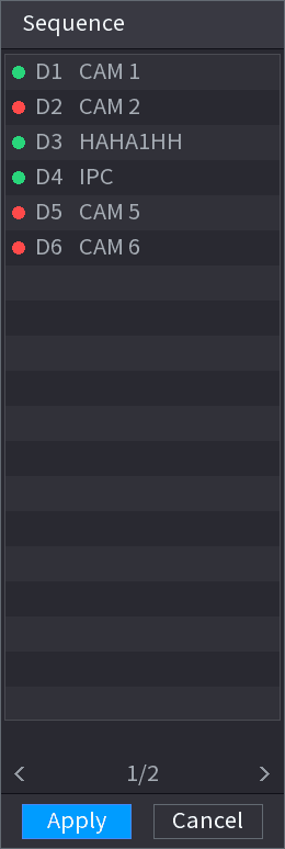
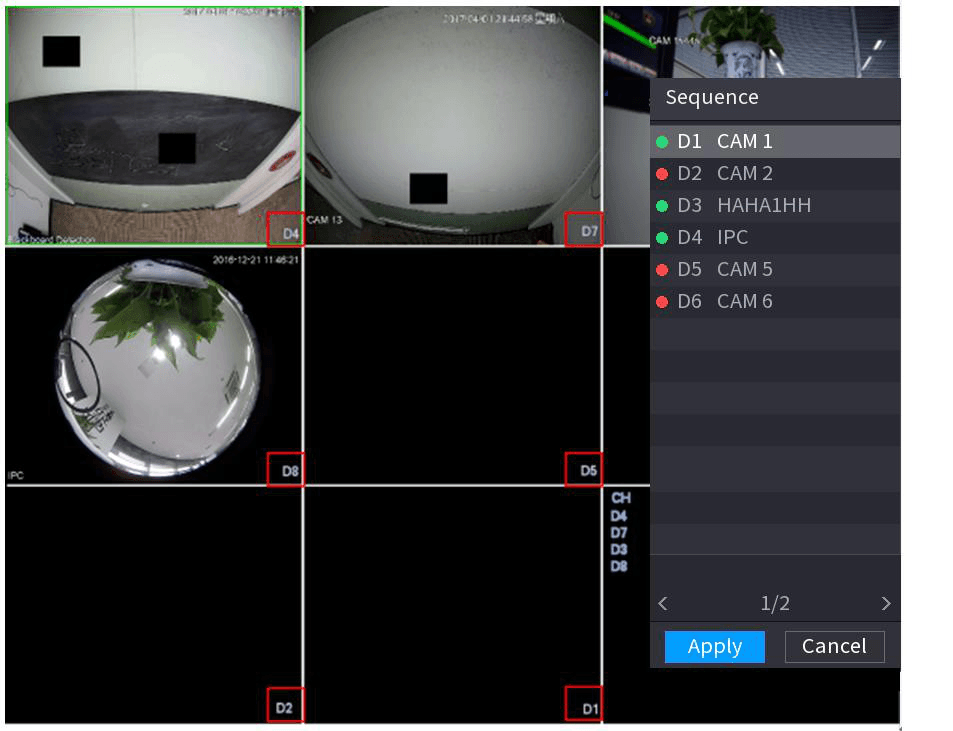
On the preview interface, right click mouse and then click Sequence. The Sequence interface is displayed. See Figure 4-70.
- Enter edit view interface, device automatically switches to the max split amount mode.
- The channel list on the edit view interface displays the added camera channel number and channel name. The green dot means camera is online. The red dot means camera is offline.
- In case the channel amount has exceeded the device max split amount, the edit view interface can display the max screen number amount and current screen number.
Arrange the channels
On the edit view interface, drag the channel to the desired window, or drag on the preview window to switch the position. Check the channel number at the right bottom corner to view the current channel sequence. See Figure 4-71.
Save the channel sequence
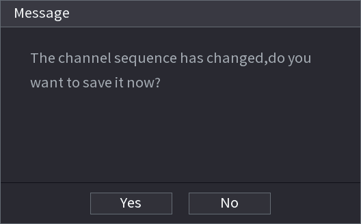
Click Apply to save current channel sequence. After you change the channel sequence, click Cancel button or right click mouse, device pops up the dialogue box. See Figure 4-72.
- Click OK to save current settings.
- Click No to exit without saving the settings.
Fisheye (Optional)
This function is for some series products only.
Fisheye de-warp during preview interface
The fisheye camera (panoramic camera) has wide video of angle but its video is seriously distorted. The de-warp function can present the proper and vivid video suitable for human eyes.
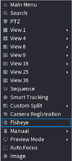
On the preview interface, select fisheye channel and then right click mouse, you can select fish eye. See Figure 4-73. You can set fisheye installation mode and display mode.
- For the non-fish eye channel, system pops up dialogue box to remind you it is not a fish eye channel and does not support de-warp function.
- If system resources are insufficient, system pops up the corresponding dialogue box too.
Now you can see an interface shown as Figure 4-74. You can set fish eye installation mode and display mode. There are three installation modes: ceiling mount/wall mount/ground mount.
- The different installations modes have different de-warp modes.
- Some series products support 180° de-warp. 180° de-warp fisheye supports wall mount de-warp only. The actual product shall prevail.
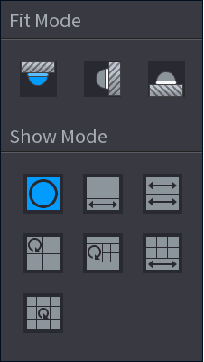
Refer to the following sheet for detailed information. See Table 4-19.
Table 4-19
| Installation modes | Note |
|---|---|
| Ceiling mount | 360° panorama original view |
| Ceiling mount | 1 de-warp window + 1 panorama stretching |
| Ceiling mount | 2 panorama stretching view |
| Ceiling mount | 1 360° panorama view + 3 de-warp windows |
| Ceiling mount | 1 360° panorama view + 4 de-warp windows |
| Ceiling mount | 4 de-warp windows + 1 panorama stretching |
| Ceiling mount | 1 360° panorama view + 8 de-warp windows |
| Wall mount | 360° panorama original view |
| Wall mount | Panorama stretching |
| Wall mount | 1 panorama unfolding view + 3 de-warp windows |
| Wall mount | 1 panorama unfolding view + 4 de-warp windows |
| Wall mount | 1 panorama unfolding view + 8 de-warp windows |
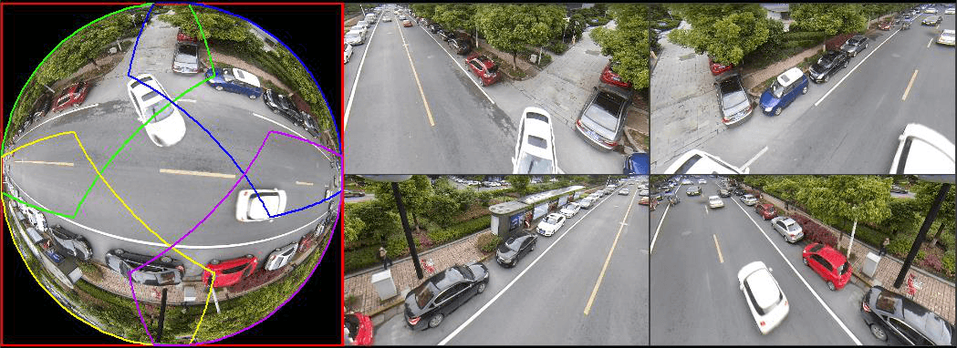
In Figure 4-75, you can adjust the color pane on the left pane or use your mouse to change the position of the small images on the right pane to realize fish eye de-warp.
Operation: Use mouse to zoom in/zoom out, move, and rotate the image (Not for wall mount mode.)
Fish eye de-warp during playback
When playing back the fisheye record file, you can use de-warp function to adjust video.
Open Backup
On the main menu, click Backup button.
Select playback mode
Select 1-window playback mode and corresponding fish eye channel, click the play button to play.
Enter de-warp playback
Right click the fisheye channel, you can go to the de-warp playback interface. For detailed information, refer to 4.3.5.1 Fisheye de-warp during preview interface.
Test Temperature
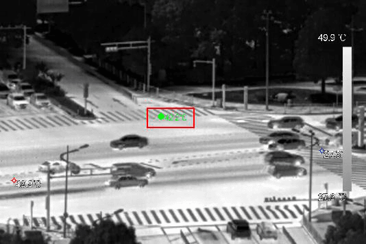
When connecting to the front-end device that supports temperature detection, system can display instant temperature.
- This function may collect the human temperature in the surveillance video, be careful!
- This function is for some series products only.
Preparations
Refer to 4.16.1 Display to enable test temperature function.
On the preview window, click any position on the thermal channel video. The interface is shown as below. See Figure 4-76.
AI Preview Mode
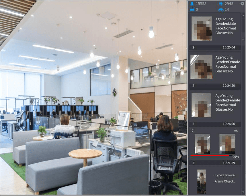
When you select AI mode, the system displays information of human face, personnel, vehicle and non-motor vehicle on the right side of the preview interface, and it supports to play back records and display feature attributes.
You need to enable face detection, body detection, vehicle detection and non-motor vehicle detection to support this function. For details, see 4.7.2.5 Video Structuring (Metadata).
Enter AI mode
Right click to select Preview Mode > AI Mode. The AI preview interface is displayed. See Figure 4-77.
Play the corresponding video
(Optional) Double-click the image on the right to play the corresponding video.
Set face attributes
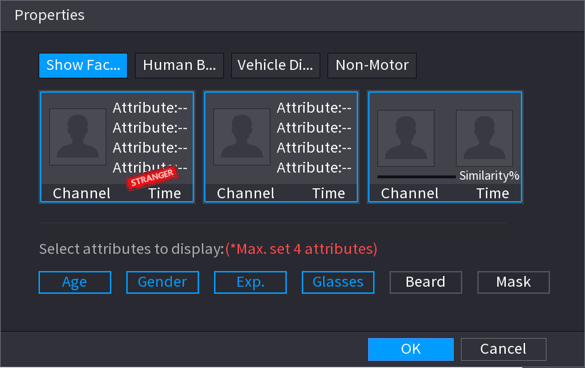
(Optional) Click Show Face List and select attributes to display, including age, gender, expression, glasses, beard and mask.
Set human body attributes
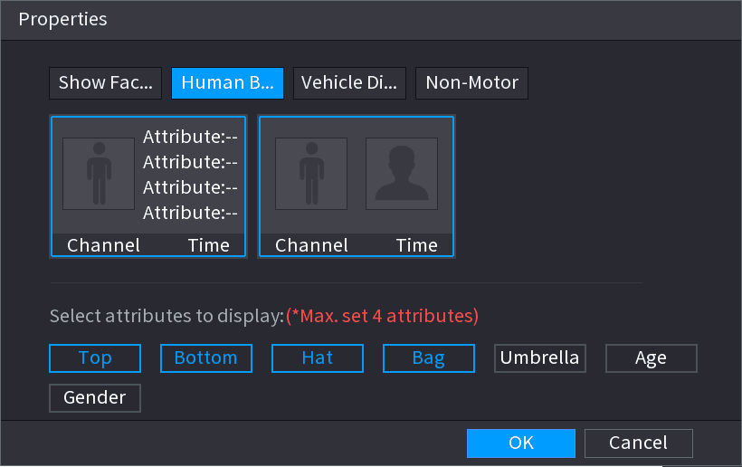
(Optional) Click Human Body Detection and select attributes to display, including top, pants, hat, bag, bag style, umbrella, age and gender. See Figure 4-79.
Set vehicle attributes
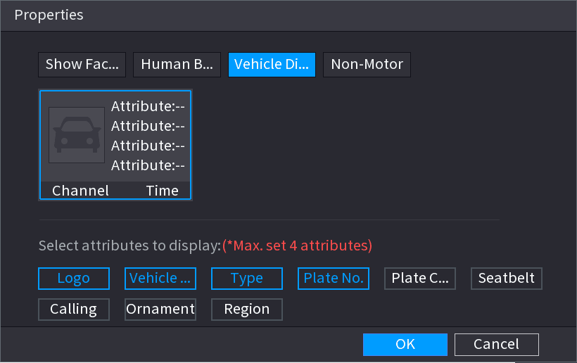
(Optional) Click Vehicle Display and select attributes to display, including vehicle logo, vehicle color, vehicle model, plate recognition, plate color, seatbelt, call, vehicle decorations and countries & regions. See Figure 4-80.
Set non-motor attributes
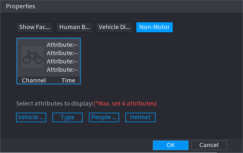
(Optional) Click Non-Motor and select attributes to display, including color, type and people number. See Figure 4-81.
Camera
Register and manage remote network cameras on the Sapphire NVR, including changing IP addresses, importing and exporting device lists, remote device initialization, image, encode and snapshot settings, channel name, remote upgrade, and remote device status and firmware information.
PTZ
Configure and control PTZ cameras on the NVR, including PTZ settings, basic and expanded control panels, and configuring and calling presets, tours, patterns, auto scan, auto pan, and AUX functions.