 LTS Connect ヘルプセンター
Front Panel and Rear Panel
Front panel indicators, buttons, and rear panel ports for every Sapphire Series NVR model, including indicator light tables and port connection tables for each chassis and PoE variant.
The following front panel and rear panel figures are for reference only. The actual product shall prevail.
Front Panel
Beneficio smart 1U / Beneficio smart 1U(S2) / 4K smart 1U (S2) / Beneficio 4K Smart 1U(S2) Series
The front panel is shown as in Figure 2-1.
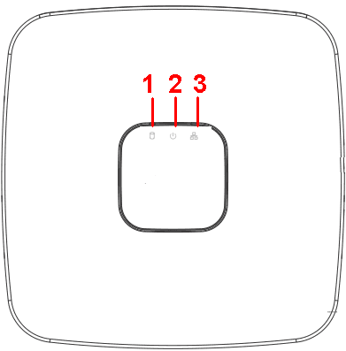
| SN | Name | Function |
|---|---|---|
| 1 | HDD status indictor light | The red light becomes on when HDD is abnormal. |
| 2 | Power indicator light | The red light becomes on when the power connection is OK. |
| 3 | Network status indicator light | The red light becomes on when the network connection is abnormal. |
Beneficio Mini 1U Series
The front panel is shown as in Figure 2-2.

| Icon | Name | Function |
|---|---|---|
| NET | Network status indicator light | The red light becomes on when the network connection is abnormal. |
| PWR | Power indicator light | The red light becomes on when the power connection is OK. |
| HDD | HDD status indictor light | The red light becomes on when HDD is abnormal. |
| IR | Remote control receiver | It is to receive signal from the remote control. |
Compact 1U Wireless Series
The front panel is shown as below. See Figure 2-3.
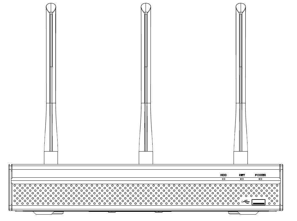
| Icon | Name | Function |
|---|---|---|
| HDD | HDD status indicator light | The blue light is on when the HDD is malfunction. |
| NET | Network status indicator light | The blue light is on when the network connection is abnormal. |
| POWER | Power status indicator light | The blue light is on when the power connection is OK. |
| USB2.0 port | Connect to peripheral USB 2.0 storage device, mouse, burner and etc. |
Beneficio Smart 1U with 8 PoE port Series
The front panel is shown as below. See Figure 2-4.
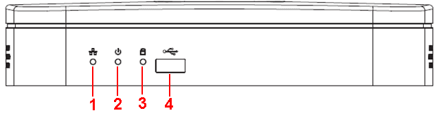
| SN | Name | Function |
|---|---|---|
| 1 | Network status indicator light | The red light becomes on when the network connection is abnormal. |
| 2 | Power indicator light | The red light becomes on when the power connection is OK. |
| 3 | HDD status indictor light | The red light becomes on when HDD is abnormal. |
| 4 | USB | USB port |
Beneficio 1U Series
The front panel is shown as below. See Figure 2-5.

| Icon | Name | Function |
|---|---|---|
| Power button | Power button, press this button for three seconds to boot up or shut down NVR. | |
| Shift | Shift | In textbox, click this button to switch between numeral, English(Small/Capitalized),donation and etc. |
| Up/1, Down/4 | \ | Activate current control, modify setup, and then move up and down. Increase/decrease numeral. Assistant function such as PTZ menu. In text mode, input number 1/4 (English character G/H/I). |
| Left/2, Right/3 | \ | Shift current activated control. When playback, click these buttons to control playback bar. In text mode, input number 2(English character A/B/C)/3(English character D/E/F). |
| ESC | ESC | Go to previous menu, or cancel current operation. When playback, click it to restore real-time monitor mode. |
| Enter | ENTER | Confirm current operation. Go to default button. Go to menu. |
| Record | REC | Manually stop/start recording, working with direction keys. or numeral keys to select the recording channel. |
| Slow play/8 | Multiple slow play speeds or normal playback. In text mode, input number 8 (English character T/U/V). | |
| Assistant | Fn | One-window monitor mode, click this button to display assistant function: PTZ control and image color. Backspace function: in numeral control or text control, press it for 1.5seconds to delete the previous character before the cursor. In motion detection setup, working with Fn and direction keys to realize setup. In text mode, click it to switch between numeral, English character(small/capitalized) and etc. |
| Fast play/7 | Various fast speeds and normal playback. In text mode, input number 7 (English character P/Q/R/S). | |
| Play previous/0 | In playback mode, playback the previous video. In text mode, input number 0. | |
| Reverse/Pause/6 | In normal playback or pause mode, click this button to reverse playback. In reverse playback, click this button to pause playback. In text mode, input number 6 (English character M/N/O). | |
| Play Next/9 | In playback mode, playback the next video. In menu setup, go to down ward of the dropdown list. In text mode, input number 9 (English character W/X/Y/Z). | |
| Play/Pause /5 | In normal playback click this button to pause playback. In pause mode, click this button to resume playback. In text mode, input number 5(English character J/K/L). | |
| USB port | To connect USB storage device, USB mouse. | |
| Network abnormal indicator light | Net | Network error occurs or there is no network connection, the light becomes red to alert you. |
| HDD abnormal indicator light | HDD | HDD error occurs or HDD capacity is below specified threshold value, the light becomes red to alert you. |
| Record light | 1-16 | System is recording or not. It becomes on when system is recording. |
| IR Receiver | IR | It is to receive the signal from the remote control. |
Compact 1U(S2)/ 4K compact 1U (S2) / Compact 1U 4K(S2) Series
The series front panel is shown as below. See Figure 2-6.

| Icon | Name | Function |
|---|---|---|
| STATUS | Status indicator light | The blue light is on when the device is malfunction. Note: General compact 1U(S2) series product does not support STATUS indicator light. |
| HDD | HDD status indicator light | The blue light is on when the HDD is malfunction. |
| NET | Network status indicator light | The blue light is on when the network connection is abnormal. |
| POWER | Power status indicator light | The blue light is on when the power connection is OK. |
| USB port | Connect to peripheral USB storage device, mouse and etc. |
1U/1.5U/2U Series
The 1U series front panel is shown as in Figure 2-7.

The 1.5U series front panel is shown as in Figure 2-8.

The 2U series front panel is shown as in Figure 2-9.
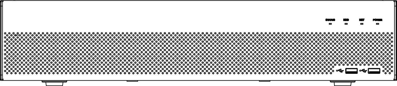
| Icon | Name | Function |
|---|---|---|
| STATUS | Status indicator light | The blue light is on when the device is malfunction. |
| HDD | HDD status indicator light | The blue light is on when the HDD is malfunction. |
| NET | Network status indicator light | The blue light is on when the network connection is abnormal. |
| POWER | Power status indicator light | The blue light is on when the power connection is OK. |
| USB2.0 port | Connect to peripheral USB 2.0 storage device, mouse, burner and etc. |
Beneficio 1.5U Series
The front panel is shown as in Figure 2-10.

| Icon | Name | Function |
|---|---|---|
| Power button | Power button, press this button for three seconds to boot up or shut down NVR. | |
| Shift | Shift | In textbox, click this button to switch between numeral, English(Small/Capitalized),donation and etc. |
| Up/1, Down/4 | \ | Activate current control, modify setup, and then move up and down. Increase/decrease numeral. Assistant function such as PTZ menu. In text mode, input number 1/4 (English character G/H/I). |
| Left/2, Right/3 | \ | Shift current activated control. When playback, click these buttons to control playback bar. In text mode, input number 2(English character A/B/C). /3(English character D/E/F). |
| ESC | ESC | Go to previous menu, or cancel current operation. When playback, click it to restore real-time monitor mode. |
| Enter | ENTER | Confirm current operation. Go to default button. Go to menu. |
| Record | REC | Manually stop/start recording, working with direction keys. or numeral keys to select the recording channel. |
| Slow play/8 | Multiple slow play speeds or normal playback. In text mode, input number 8 (English character T/U/V). | |
| Assistant | Fn | One-window monitor mode, click this button to display assistant function: PTZ control and image color. Backspace function: in numeral control or text control, press it for 1.5seconds to delete the previous character before the cursor. In motion detection setup, working with Fn and direction keys to realize setup. In text mode, click it to switch between numeral, English character(small/capitalized) and etc. |
| Fast play/7 | Various fast speeds and normal playback. In text mode, input number 7 (English character P/Q/R/S). | |
| Play previous/0 | In playback mode, playback the previous video. In text mode, input number 0. | |
| Reverse/Pause/6 | In normal playback or pause mode, click this button to reverse playback. In reverse playback, click this button to pause playback. In text mode, input number 6 (English character M/N/O). | |
| Play Next/9 | In playback mode, playback the next video. In menu setup, go to down ward of the dropdown list. In text mode, input number 9 (English character W/X/Y/Z). | |
| Play/Pause /5 | In normal playback click this button to pause playback. In pause mode, click this button to resume playback. In text mode, input number 5(English character J/K/L). | |
| USB port | To connect USB storage device, USB mouse. | |
| Network abnormal indicator light | Net | Network error occurs or there is no network connection, the light becomes red to alert you. |
| HDD abnormal indicator light | HDD | HDD error occurs or HDD capacity is below specified threshold value, the light becomes red to alert you. |
| Record light | 1-16 | System is recording or not. It becomes on when system is recording. |
Beneficio 2U Series
The Front panel is shown as follows. See Figure 2-11.
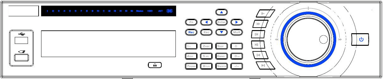
| Icon | Name | Function |
|---|---|---|
| Power button | Power button, press this button for three seconds to boot up or shut down NVR. | |
| Number button | 0-9 | Input Arabic number. Switch channel. |
| Input number more than 10 | -/-- | If you want to input a number more than 10, please click this button and then input. |
| Shift | In textbox, click this button to switch between numeral, English(Small/Capitalized),donation and etc. Enable or disable tour. | |
| Up/Down | \ | Activate current control, modify setup, and then move up and down. Increase/decrease numeral. Assistant function such as PTZ menu. |
| Left/Right | \ | Shift current activated control, and then move left and right. When playback, click these buttons to control playback bar. |
| ESC | ESC | Go to previous menu, or cancel current operation. When playback, click it to restore real-time monitor mode. |
| Enter | ENTER | Confirm current operation. Go to default button. Go to menu. |
| Record | REC | Manually stop/start recording, working with direction keys or numeral keys to select the recording channel. |
| Slow play | Multiple slow play speeds or normal playback. | |
| Assistant | Fn | One-window monitor mode, click this button to display assistant function: PTZ control and image color. Backspace function: in numeral control or text control, press it for 1.5seconds to delete the previous character before the cursor. In motion detection setup, working with Fn and direction keys to realize setup. In text mode, click it to switch between numeral, English character(small/capitalized) and etc. In HDD management interface, you can click it to switch HDD record information and other information (Menu prompt). Realize other special functions. |
| Fast play | Various fast speeds and normal playback. | |
| Play previous | In playback mode, playback the previous video. | |
| Reverse/Pause | In normal playback or pause mode, click this button to reverse playback. In reverse playback, click this button to pause playback. | |
| Play Next | In playback mode, playback the next video. In menu setup, go to down ward of the dropdown list. | |
| Play/Pause | In normal playback click this button to pause playback. In pause mode, click this button to resume playback. | |
| Window switch | Mult | Click it to switch one-window/multiple-window. |
| Shuttle(outer ring) | In real-time monitor mode it works as left/right direction key. Playback mode, counter clockwise to forward and clock wise to backward. | |
| Jog(inner dial) | Up/down direction key. Playback mode, turn the inner dial to realized frame by frame playback. (Only applies to some special versions.) | |
| USB port | To connect USB storage device, USB mouse. | |
| Remote control indicator light | ACT | Remote control indicator light. |
| Status indicator light | Status | If there is Fn indicator light, current status indicator light is null. |
| Power indicator light | PWR | Power indicator light. |
| Channel indictor light | 1-32 | For 4/8/16-channel series product. The corresponding channel light becomes on when system is recording. For 32/64-channel series product: When the light flashes slowly, it means the corresponding channel of 1-16 channel is recording now (Such as channel 1). When the light flashes fast, it means the corresponding channel of 17-32 channel is recording now (Such as channel 17). When the light becomes on, It means the corresponding 2 channels are recoding now (Such as channel 1 and channel 17.). The channel indictor light here does not show the status of the 33-64-channel. |
| IR Receiver | IR | It is to receive the signal from the remote control. |
Beneficio Vertical 1U Series
The front panel is shown as below. See Figure 2-12.
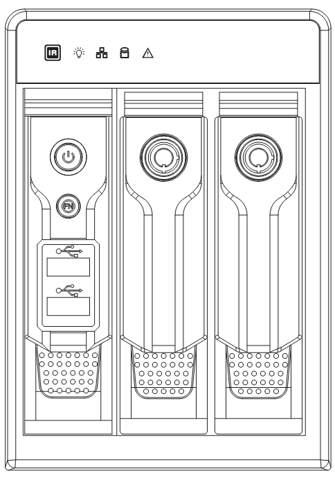
| Name | Icon | Function |
|---|---|---|
| Power button | Power button, press this button for three seconds to boot up or shut down NVR. | |
| Assistant | Fn | One-window monitor mode, click this button to display assistant function: PTZ control and image color. Backspace function: in numeral control or text control, press it for 1.5 seconds to delete the previous character before the cursor. In motion detection setup, working with Fn and direction keys to realize setup. In text mode, click it to switch between numeral, English character (small/capitalized) and etc. In HDD management interface, you can click it to switch HDD record information and other information (Menu prompt). Realize other special functions. |
| USB2.0 port | To connect USB2.0 storage device, USB2.0 mouse, burner and etc. | |
| IR receive window | It is to receive the IR signal from the remote control. | |
| Power indicator light | Power indicator light. | |
| HDD abnormal indicator light | HDD error occurs or HDD capacity is below specified threshold value, the light becomes red to alert you. | |
| Network abnormal indicator light | Network error occurs or there is no network connection, the light becomes red to alert you. | |
| Alarm indicator light | The light becomes on when an alarm occurred. |
Smart 1U 4K (S2) with Wireless Series
The front panel is shown as below. See Figure 2-13.
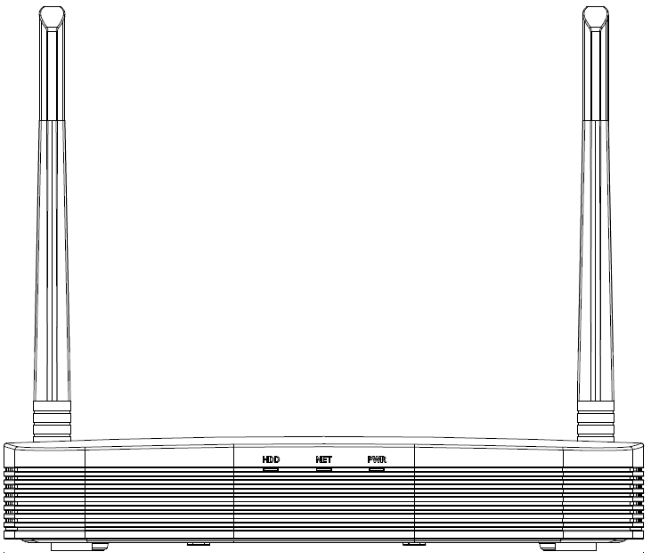
| Icon | Name | Function |
|---|---|---|
| HDD | HDD status indicator light | The blue light is on when the HDD is malfunction. |
| NET | Network status indicator light | The blue light is on when the network connection is abnormal. |
| PWR | Power status indicator light | The blue light is on when the power connection is OK. |
Compact 1U 4K (S2) with Wireless Series
The front panel is shown as below. See Figure 2-14.
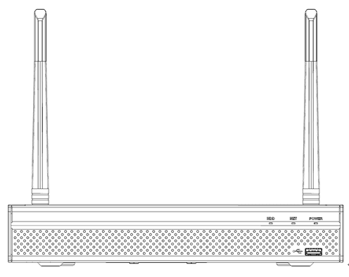
| Icon | Name | Function |
|---|---|---|
| HDD | HDD status indicator light | The blue light is on when the HDD is malfunction. |
| NET | Network status indicator light | The blue light is on when the network connection is abnormal. |
| POWER | Power status indicator light | The blue light is on when the power connection is OK. |
| USB2.0 port | Connect to peripheral USB 2.0 storage device, mouse and etc. |
Cooper 1U (S3) / Cooper 1U (S3) with 4 PoE Ports / Compact 1U (S3) with 8 PoE Ports Series
The Cooper 1U (S3) / Cooper 1U (S3) with 4 PoE Ports series NVR front panel is shown as in Figure 2-15.
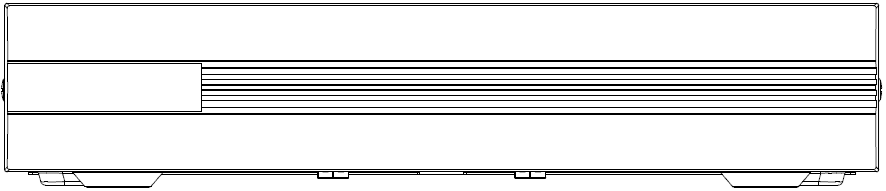
The Compact 1U (S3) with 8 PoE Ports series NVR front panel is shown as in Figure 2-16.

Rear Panel
Beneficio Smart 1U / Beneficio Smart 1U with 1 PoE port / Beneficio Smart 1U with 8 PoE ports / Beneficio Smart 1U with wireless Series
The beneficio Smart 1U series NVR rear panel is shown as below. See Figure 2-17.
The beneficio Smart 1U with 1 PoE port series NVR rear panel is shown as below. See Figure 2-18.
The beneficio Smart 1U with 8 PoE ports series NVR rear panel is shown as below. See Figure 2-19.
The Beneficio Smart 1U with wireless series NVR rear panel is shown as below. See Figure 2-20.
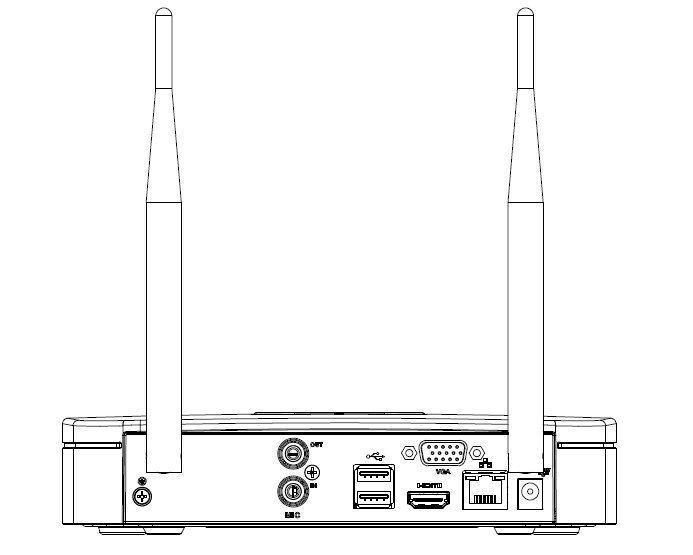
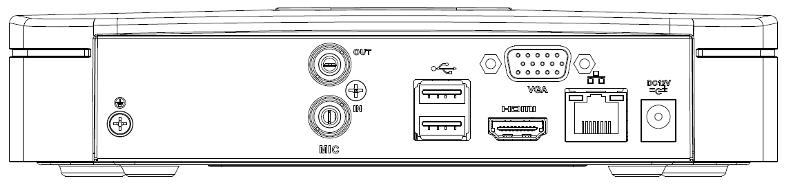
| Port Name | Connection | Function |
|---|---|---|
| USB2.0 port | USB2.0 port. Connect to mouse, USB storage device, USB burner and etc. | |
| Network port | 10M/100Mbps self-adaptive Ethernet port. Connect to the network cable. | |
| HDMI | High Definition Media Interface | High definition audio and video signal output port. It transmits uncompressed high definition video and multiple-channel data to the HDMI port of the display device. HDMI version is 1.4. |
| VGA | VGA video output port | VGA video output port. Output analog video signal. It can connect to the monitor to view analog video. |
| GND | Ground end | |
| / | Power input port | Power socket. For beneficio smart 1U series, input DC 12V/2A. For beneficio smart 1U with 1 PoE port series, input DC 48V/1.5A. For beneficio smart 1U with 8 PoE ports series, input DC 48V/2A. |
| MIC IN | Audio input port | Bidirectional talk input port. It is to receive the analog audio signal output from the devices such as microphone, pickup. |
| MIC OUT | Audio output port | Audio output port. It is to output the analog audio signal to the devices such as the sound box. Bidirectional talk output. Audio output on 1-window video monitor. Audio output on 1-window video playback. |
| PoE PORT | PoE port | Built-in switch. Support PoE function. For PoE series product, you can use this port to provide power to the network camera. |
| Wireless AP | Support wireless hotspot function. Use WIFI to connect to the network camera when there is a hotspot. For Beneficio Smart 1U with wireless series NVR only. |
Beneficio Smart 1U (S2) / Beneficio 4K Smart 1U(S2) Series
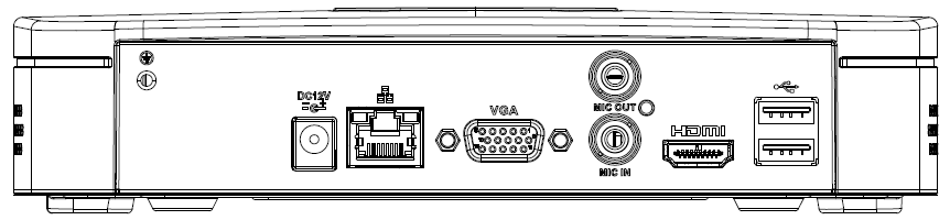
The general series is shown as in Figure 2-21.
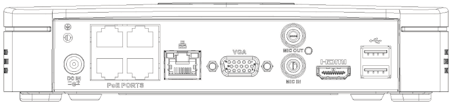
The 4 PoE ports series is shown as in Figure 2-22.
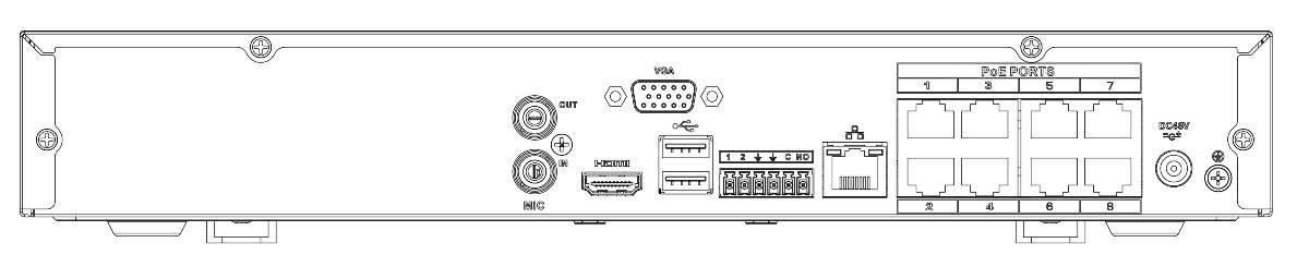
The 8 PoE ports series is shown as in Figure 2-23.

| Port Name | Connection | Function |
|---|---|---|
| Power input port | Power socket. For general series,input DC 12V/2A. For 4 PoE ports series,input DC 48V/1.25A. For 8 PoE ports series,input DC 48V/2A. | |
| Network port | 10M/100Mbps self-adaptive Ethernet port. Connect to the network cable. | |
| USB port | USB port. Connect to mouse, USB storage device and etc. | |
| HDMI | High Definition Media Interface | High definition audio and video signal output port. It transmits uncompressed high definition video and multiple-channel data to the HDMI port of the display device. HDMI version is 1.4. |
| VGA | VGA video output port | VGA video output port. Output analog video signal. It can connect to the monitor to view analog video. |
| MIC IN | Audio input port | Bidirectional talk input port. It is to receive the analog audio signal output from the devices such as microphone, pickup. |
| MIC OUT | Audio output port | Audio output port. It is to output the analog audio signal to the devices such as the sound box. Bidirectional talk output. Audio output on 1-window video monitor. Audio output on 1-window video playback. |
| GND | Ground end | |
| PoE PORTS | PoE port | Built-in switch. Support PoE function. For PoE series product, you can use this port to provide power to the network camera. |
Beneficio Mini 1U / Beneficio Mini 1U with 1 PoE port / Beneficio Mini 1U with 8 PoE ports Series
The beneficio mini 1U series NVR rear panel is shown as in Figure 2-24.

The beneficio mini 1U with 1 PoE port series NVR rear panel is shown as in Figure 2-25.

The beneficio mini 1U with 8 PoE ports series NVR rear panel is shown as in Figure 2-26.
| Port Name | Connection | Function |
|---|---|---|
| USB2.0 port | USB2.0 port. Connect to mouse, USB storage device, USB burner and etc. | |
| Network port | 10M/100Mbps self-adaptive Ethernet port. Connect to the network cable. | |
| HDMI | High Definition Media Interface | High definition audio and video signal output port. It transmits uncompressed high definition video and multiple-channel data to the HDMI port of the display device. HDMI version is 1.4. |
| VGA | VGA video output port | VGA video output port. Output analog video signal. It can connect to the monitor to view analog video. |
| GND | Ground end | |
| / | Power input port | Power socket. For beneficio mini 1U series NVR, input DC 12V/2A. For beneficio mini 1U with 1 PoE port series NVR, input DC 48V/1.5A. For beneficio Mini 1U with 8 PoE ports series NVR, input DC 48V/2A. |
| MIC IN | Audio input port | Bidirectional talk input port. It is to receive the analog audio signal output from the devices such as microphone, pickup. |
| MIC OUT | Audio output port | Audio output port. It is to output the analog audio signal to the devices such as the sound box. Bidirectional talk output. Audio output on 1-window video monitor. Audio output on 1-window video playback. |
| PoE PORT | PoE port | Built-in switch. Support PoE function. For PoE series product, you can use this port to provide power to the network camera. |
Compact 1U(S2)/ Compact 1U 4K(S2)Series
The general series rear panel is shown as below. See Figure 2-27.

The 4 PoE ports series rear panel is shown as below. See Figure 2-28.

The 8 PoE ports series rear panel is shown as below. See Figure 2-29.

| Port Name | Connection | Function |
|---|---|---|
| Power input port | Power socket. For general series, input DC 12V/2A. For 4 PoE ports series, input DC 48V/1.25A. For 8 PoE ports series, input DC 48V/2A. | |
| Network port | 10M/100Mbps self-adaptive Ethernet port. Connect to the network cable. | |
| USB port | USB port. Connect to mouse, USB storage device and etc. | |
| HDMI | High Definition Media Interface | High definition audio and video signal output port. It transmits uncompressed high definition video and multiple-channel data to the HDMI port of the display device. HDMI version is 1.4. |
| VGA | VGA video output port | VGA video output port. Output analog video signal. It can connect to the monitor to view analog video. |
| MIC IN | Audio input port | Bidirectional talk input port. It is to receive the analog audio signal output from the devices such as microphone, pickup. |
| MIC OUT | Audio output port | Audio output port. It is to output the analog audio signal to the devices such as the sound box. Bidirectional talk output. Audio output on 1-window video monitor. Audio output on 1-window video playback. |
| GND | Ground end | |
| PoE PORTS | PoE port | Built-in switch. Support PoE function. For PoE series product, you can use this port to provide power to the network camera. |
Compact 1U Wireless Series
The rear panel is shown as below. See Figure 2-30.
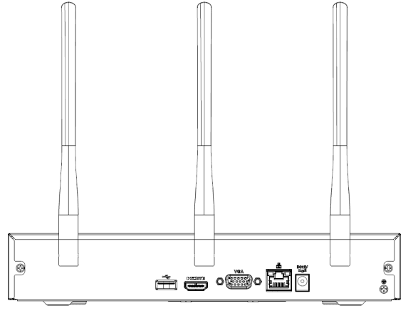
| Icon | Name | Function |
|---|---|---|
| Power input socket | Power socket. Input DC12V/2A. | |
| Network port | 10M/100Mbps self-adaptive Ethernet port. Connect to the network cable. | |
| USB2.0 port | USB2.0 port. Connect to mouse, USB storage device, and etc. | |
| HDMI | High Definition Media Interface | High definition audio and video signal output port. It transmits uncompressed high definition video and multiple-channel data to the HDMI port of the display device. HDMI version is 1.4. |
| VGA | VGA video output port | VGA video output port. Output analog video signal. It can connect to the monitor to view analog video. |
| GND | Ground end | |
| Wireless AP | Support wireless hotspot function. Use WIFI to connect to the network camera when there is a hotspot. |
Beneficio 1U (S2) / Beneficio 4K 1U(S2) Series
The general series rear panel is shown as below. See Figure 2-31.

The 4 PoE ports series rear panel is shown as below. See Figure 2-32.

The 8 PoE ports series rear panel is shown as below. See Figure 2-33.

| Port Name | Connection | Function |
|---|---|---|
| Power input port | Power socket. For general series, input DC 12V/4A. For 4 PoE ports series, input DC 48V/1.5A. For 8 PoE ports series, input DC 53V 120W. | |
| Network port | 10M/100Mbps self-adaptive Ethernet port. Connect to the network cable. | |
| USB port | USB port. Connect to mouse, USB storage device and etc. | |
| HDMI | High Definition Media Interface | High definition audio and video signal output port. It transmits uncompressed high definition video and multiple-channel data to the HDMI port of the display device. HDMI version is 1.4. |
| VGA | VGA video output port | VGA video output port. Output analog video signal. It can connect to the monitor to view analog video. |
| MIC IN | Audio input port | Bidirectional talk input port. It is to receive the analog audio signal output from the devices such as microphone, pickup. |
| MIC OUT | Audio output port | Audio output port. It is to output the analog audio signal to the devices such as the sound box. Bidirectional talk output. Audio output on 1-window video monitor. Audio output on 1-window video playback. |
| GND | Ground end | |
| PoE PORTS | PoE port | Built-in switch. Support PoE function. For PoE series product, you can use this port to provide power to the network camera. |
Beneficio 1U / Beneficio Entry-level 1U / Beneficio 1U with 1 PoE port / Beneficio 1U with 8 PoE ports / Beneficio 1U with 16 PoE Ports Series
The beneficio 1U series NVR rear panel is shown as below. See Figure 2-34.

The beneficio entry-level 1U series rear panel is shown as below. See Figure 2-35.

The beneficio 1U with 1 PoE port series NVR rear panel is shown as below. See Figure 2-36.

The beneficio 1U with 8 PoE ports series NVR rear panel is shown as below. See Figure 2-37.

The beneficio 1U with 16 PoE Ports series rear panel is shown as below. See Figure 2-38.

| Name | Function |
|---|---|
| Power switch | Power on/off button. |
| Power input port | Input DC 12V/5A. For beneficio 1U series product only. Switch power port. Input DC 48//1.04A. For beneficio 1U with 1 PoE port series product only. Input AC 100~240V. For beneficio 1U with 8/16 PoE ports series product only. |
| MIC IN — Audio input port | Bidirectional talk input port. It is to receive the analog audio signal output from the devices such as microphone, pickup. |
| MIC OUT — Audio output port | Audio output port. It is to output the analog audio signal to the devices such as the sound box. Bidirectional talk output. Audio output on 1-window video monitor. Audio output on 1-window video playback. |
| 1~4 — Alarm input port 1~4 | There are two types; NO (normal open)/NC (normal close). When your alarm input device is using external power, please make sure the device and the NVR have the same ground. |
| GND | Alarm input ground port. |
| N1, N2 / C1, C2 — Alarm output port 1~2 | 2 groups of alarm output ports. (Group 1:port NO1~C1, Group 2: port NO2~C2). Output alarm signal to the alarm device. Please make sure there is power to the external alarm device. NO:Normal open alarm output port. C:Alarm output public end. |
| A — RS-485 communication port | RS485_A port. It is the cable A. You can connect to the control devices such as speed dome PTZ. |
| B — RS-485 communication port | RS485_B. It is the cable B. You can connect to the control devices such as speed dome PTZ. |
| Network port | 10M/100M/1000Mbps self-adaptive Ethernet port. Connect to the network cable. |
| USB2.0 port | USB2.0 port. Connect to mouse, USB storage device, USB burner and etc. |
| RS-232 — RS-232 debug COM. | It is for general COM debug to configure IP address or transfer transparent COM data. |
| HDMI — High Definition Media Interface | High definition audio and video signal output port. It transmits uncompressed high definition video and multiple-channel data to the HDMI port of the display device. HDMI version is 1.4. |
| VGA — VGA video output port | VGA video output port. Output analog video signal. It can connect to the monitor to view analog video. |
| PoE PORTS | Built-in Switch. Support PoE. The 4 PoE series product supports total 48V 50W. The 8 PoE series product supports total 48V 120W. The 16 PoE series product supports total 120W. One PoE port max supports 15W. |
Professional 4K 1U / Professional 4K 1U with 8 PoE ports / Professional 4K 1U with 16 PoE ports / 4K 1U (S2) with 24 PoE Ports / 4K 1U (S2E) with 8 PoE ports / 4K 1U (S2E) with 16 PoE ports Series
The professional 4K 1U series rear panel is shown as below. See Figure 2-39.

The professional 4K 1U with 8 PoE ports rear panel is shown as below. See Figure 2-40.

The professional 4K 1U with 16 PoE ports rear panel is shown as below. See Figure 2-41.

The 4K 1U (S2) with 24 PoE ports series rear panel is shown as below. See Figure 2-42.

The 4K 1U (S2E) with 8 PoE ports / 4K 1U (S2E) with 16 PoE ports series rear panel is shown as below. See Figure 2-43.
The following figure takes 4K 1U (S2E) with 16 PoE ports series as an example.

| Icon | Port Name | Function |
|---|---|---|
| Network port | 10M/100M/1000Mbps self-adaptive Ethernet port. Connect to the network cable. | |
| HDMI | High Definition Media Interface | High definition audio and video signal output port. It transmits uncompressed high definition video and multiple-channel data to the HDMI port of the display device. HDMI version is 1.4. |
| USB3.0 port | USB3.0 port. Connect to mouse, USB storage device, USB burner and etc. | |
| RS-232 | RS-232 debug COM. | It is for general COM debug to configure IP address or transfer transparent COM data. |
| VGA | VGA video output port | VGA video output port. Output analog video signal. It can connect to the monitor to view analog video. |
| MIC IN | Audio input port | Bidirectional talk input port. It is to receive the analog audio signal output from the devices such as microphone, pickup. |
| MIC OUT | Audio output port | Audio output port. It is to output the analog audio signal to the devices such as the sound box. Bidirectional talk output. Audio output on 1-window video monitor. Audio output on 1-window video playback. |
| 1~8 | Alarm input port 1~8 | There are two groups. The first group is from port 1 to port 4; the second group is from port 5 to port 8. They are to receive the signal from the external alarm source. There are two types; NO (normal open)/NC (normal close). When your alarm input device is using external power, please make sure the device and the NVR have the same ground. |
| GND | Alarm input ground port. | |
| NO1~NO3 / C1~C3 | Alarm output port 1~3 | 3 groups of alarm output ports. (Group 1:port NO1~C1, Group 2: port NO2~C2, Group 3: port NO3~C3). Output alarm signal to the alarm device. Please make sure there is power to the external alarm device. NO:Normal open alarm output port. C:Alarm output public end. |
| A | RS-485 communication port | RS485_A port. It is the cable A. You can connect to the control devices such as speed dome PTZ. |
| B | RS-485 communication port | RS485_B. It is the cable B. You can connect to the control devices such as speed dome PTZ. |
| Power input port | Input DC 12V/4A. | |
| Power switch | / | Power on/off button. |
| PoE PORTS | / | Built-in Switch. Support PoE or ePoE function. For ePoE series product, port 1 to port 8 are the ePoE ports. ePoE port supports 300 meters@100Mbps, 800 meters@10Mbps. Port 9 to port 16 are general PoE ports. The 8 PoE series product supports total 130W. The 16 PoE series product supports total 130W. |
Beneficio 1.5U / Beneficio 1.5U with 8 PoE ports / Beneficio 1.5U with 16 PoE ports Series
The beneficio 1.5U series NVR rear panel is shown as below. See Figure 2-44.

The beneficio 1.5U with eight PoE ports series NVR rear panel is shown as below. See Figure 2-45.

The Beneficio 1.5U with sixteen PoE ports series NVR rear panel is shown as below. See Figure 2-46.

| Name | Function |
|---|---|
| Power switch | Power on-off button |
| Power input port | Input AC 100~240V. |
| MIC IN — Audio input port | Bidirectional talk input port. It is to receive the analog audio signal output from the devices such as microphone, pickup. |
| MIC OUT — Audio output port | Audio output port. It is to output the analog audio signal to the devices such as the sound box. Bidirectional talk output. Audio output on 1-window video monitor. Audio output on 1-window video playback. |
| VIDEO OUT — Video output port | CVBS output |
| 1~16 — Alarm input port 1~16 | There are four groups. The first group is from port 1 to port 4, the second group is from port 5 to port 8, the third group is from 9 to 12, and the fourth group is from 13 to 16. They are to receive the signal from the external alarm source. There are two types; NO (normal open)/NC (normal close). When your alarm input device is using external power, please make sure the device and the NVR have the same ground. |
| Video output port | CVBS output |
| NO1~NO5 / C1~C5 / NC5 — Alarm output port 1~5 | 5 groups of alarm output ports. (Group 1:port NO1~C1, Group 2: port NO2~C2, Group 3: port NO3~C3, Group 4:port NO4~C4, Group 5: port NO5, C5, NC5). Output alarm signal to the alarm device. Please make sure there is power to the external alarm device. NO: Normal open alarm output port. C: Alarm output public end. NC: Normal close alarm output port. |
| A — RS-485 communication port | RS485_A port. It is the cable A. You can connect to the control devices such as speed dome PTZ. |
| B — RS-485 communication port | RS485_B. It is the cable B. You can connect to the control devices such as speed dome PTZ. |
| CTRL 12V | Controller 12V power output. It is to control the on-off alarm relay output. It can be used to control the device alarm output. At the same time, it can also be used as the power input source of some devices such as the alarm detector. |
| +12V | +12V power output port. It can provide the power to some peripheral devices such as the camera or the alarm device. Please note the supplying power shall be below 1A. |
| Network port | 10M/100M/1000Mbps self-adaptive Ethernet port. Connect to the network cable. |
| eSATA — eSATA port | External SATA port. It can connect to the device of the SATA port. Please jump the HDD when there is peripheral connected HDD. |
| USB2.0 port | USB2.0 port. Connect to mouse, USB storage device, USB burner and etc. |
| RS-232 — RS232 debug COM. | It is for general COM debug to configure IP address or transfer transparent COM data. |
| HDMI — High Definition Media Interface | High definition audio and video signal output port. It transmits uncompressed high definition video and multiple-channel data to the HDMI port of the display device. HDMI version is 1.3 |
| VGA — VGA video output port | VGA video output port. Output analog video signal. It can connect to the monitor to view analog video. |
| PoE PORTS — 8 PoE ports | Built-in Switch. Support PoE. The 8 PoE ports series products supports total 48V 120W power. One PoE port max supports 15W. |
| PoE PORTS — 16 PoE ports | Built-in Switch. Support PoE. The 16 PoE ports series products supports total 150W power. One PoE port max supports 15W. |
Professional 4K 1.5U / Professional 4K 1.5U with 16 PoE ports / Professional 4K 2U / Professional 4K 2U with 16 PoE ports / 4K 1.5U (S2) with 24 PoE ports / 4K 1.5U (S2E) with 16 PoE Ports / 4K 2U (S2E) with 16 PoE ports Series
The professional 4K 1.5U / professional 4K 2U series rear panel is shown as below. See Figure 2-47.

The professional 4K 1.5U with 16 PoE ports / professional 4K 2U with 16 PoE ports series rear panel is shown as below. See Figure 2-48.

The 4K 1U (S2) with 24 PoE ports series rear panel is shown as below. See Figure 2-49.

The 4K 1.5U (S2E) with 16 PoE ports series rear panel is shown as below. See Figure 2-50.

The 4K 2U (S2E) with 16 PoE ports series rear panel is shown as below. See Figure 2-51.
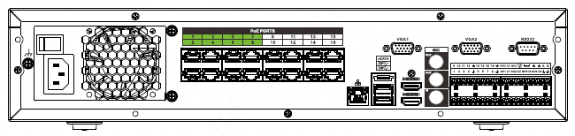
| Name | Function |
|---|---|
| Power switch | Power on-off button |
| Power input port | Input AC 100~240V. |
| Network port | 10M/100M/1000Mbps self-adaptive Ethernet port. Connect to the network cable. |
| eSATA — eSATA port | External SATA port. It can connect to the device of the SATA port. Please jump the HDD when there is peripheral connected HDD. |
| USB3.0 port | USB3.0 port. Connect to mouse, USB storage device, USB burner and etc. |
| HDMI — High Definition Media Interface | High definition audio and video signal output port. It transmits uncompressed high definition video and multiple-channel data to the HDMI port of the display device. HDMI version is 1.4b. |
| MIC IN — Audio input port | Bidirectional talk input port. It is to receive the analog audio signal output from the devices such as microphone, pickup. |
| MIC OUT — Audio output port | Audio output port. It is to output the analog audio signal to the devices such as the sound box. Bidirectional talk output. Audio output on 1-window video monitor. Audio output on 1-window video playback. |
| 1~16 — Alarm input port 1~16 | There are four groups. The first group is from port 1 to port 4, the second group is from port 5 to port 8, the third group is from 9 to 12, and the fourth group is from 13 to 16. They are to receive the signal from the external alarm source. There are two types; NO (normal open)/NC (normal close). When your alarm input device is using external power, please make sure the device and the NVR have the same ground. |
| Ground | Alarm input ground end. |
| NO1~NO5 / C1~C5 / NC5 — Alarm output port 1~5 | 5 groups of alarm output ports. (Group 1:port NO1~C1, Group 2: port NO2~C2, Group 3: port NO3~C3, Group 4:port NO4~C4, Group 5: port NO5, C5, NC5). Output alarm signal to the alarm device. Please make sure there is power to the external alarm device. NO: Normal open alarm output port. C: Alarm output public end. NC: Normal close alarm output port. |
| A — RS-485 communication port | RS485_A port. It is the cable A. You can connect to the control devices such as speed dome PTZ. |
| B — RS-485 communication port | RS485_B. It is the cable B. You can connect to the control devices such as speed dome PTZ. |
| CTRL 12V | Controller 12V power output. It is to control the on-off alarm relay output. It can be used to control the device alarm output. At the same time, it can also be used as the power input source of some devices such as the alarm detector. |
| +12V | +12V power output port. It can provide the power to some peripheral devices such as the camera or the alarm device. Please note the supplying power shall be below 1A. |
| RS-232 — RS232 debug COM. | It is for general COM debug to configure IP address or transfer transparent COM data. |
| VGA — VGA video output port | VGA video output port. Output analog video signal. It can connect to the monitor to view analog video. |
| PoE PORTS | Built-in Switch. Support PoE or ePoE function. For ePoE series product, port 1 to port 8 are the ePoE ports. ePoE port supports 300 meters@100Mbps, 800 meters@10Mbps. Port 9 to port 16 are general PoE ports. The 16 PoE series product supports total 150W. |
4K Smart 1U (S2) Series
The general 4K smart 1U (S2) series rear panel is shown as below. See Figure 2-52.
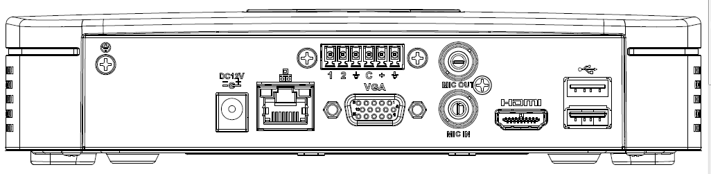
The 4K smart 1U (S2) with four PoE ports series rear panel is shown as below. See Figure 2-53.
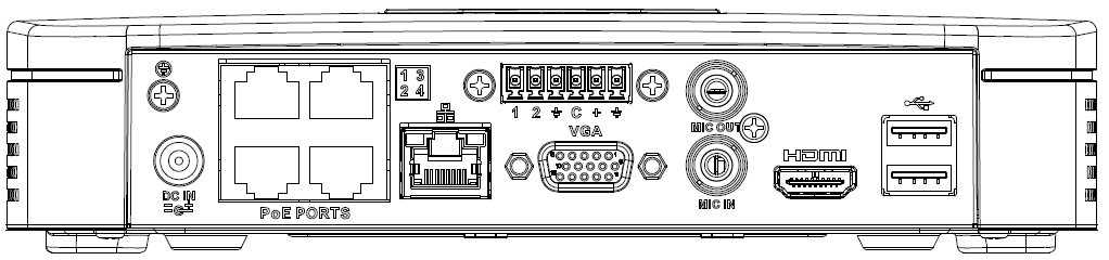
The 4K smart 1U (S2) with eight PoE ports series rear panel is shown as below. See Figure 2-54.

| Port Name | Connection | Function |
|---|---|---|
| USB port | USB port. Connect to mouse, USB storage device, USB burner and etc. | |
| Network port | 10M/100Mbps self-adaptive Ethernet port. Connect to the network cable. | |
| HDMI | High Definition Media Interface | High definition audio and video signal output port. It transmits uncompressed high definition video and multiple-channel data to the HDMI port of the display device. HDMI version is 1.4. |
| VGA | VGA video output port | VGA video output port. Output analog video signal. It can connect to the monitor to view analog video. |
| GND | Ground end | |
| / | Power input port | Power socket. For general 4K smart 1U (S2): DC 12V/2A power. For 4K smart 1U (S2) with four PoE ports: DC 48V/72W power. For 4K smart 1U (S2) with eight PoE ports: DC 48V/96W power. |
| MIC IN | Audio input port | Bidirectional talk input port. It is to receive the analog audio signal output from the devices such as microphone, pickup. |
| MIC OUT | Audio output port | Audio output port. It is to output the analog audio signal to the devices such as the sound box. Bidirectional talk output. Audio output on 1-window video monitor. Audio output on 1-window video playback. |
| PoE PORT | PoE port | Built-in switch. Support PoE function. For PoE series product, you can use this port to provide power to the network camera. |
Beneficio Vertical 1U Series
The interface is shown as in Figure 2-55.
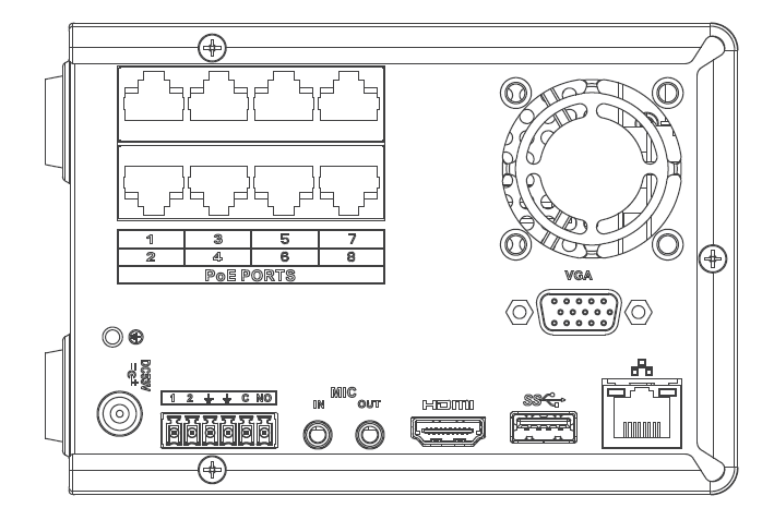
| Name | Function |
|---|---|
| Power switch | Power on/off button. |
| Power input port | Input DC 53V--2.3A |
| MIC IN — Audio input port | Bidirectional talk input port. It is to receive the analog audio signal output from the devices such as microphone, pickup. |
| MIC OUT — Audio output port | Audio output port. It is to output the analog audio signal to the devices such as the sound box. Bidirectional talk output. Audio output on 1-window video monitor. Audio output on 1-window video playback. |
| 1~2 — Alarm input port 1~2 | When your alarm input device is using external power, please make sure the device and the NVR have the same ground. |
| GND | Alarm input ground port. |
| C — Alarm output public port | Alarm output public end. |
| NO — Normal open | Normal open alarm output port. |
| Network port | 10M/100M/1000Mbps self-adaptive Ethernet port. Connect to the network cable. |
| USB3.0 port | USB3.0 port. Connect to mouse, USB storage device, USB burner and etc. |
| HDMI — High Definition Media Interface | High definition audio and video signal output port. It transmits uncompressed high definition video and multiple-channel data to the HDMI port of the display device. HDMI version is 1.4. |
| VGA — VGA video output port | VGA video output port. Output analog video signal. It can connect to the monitor to view analog video. |
| PoE PORT | Built-in Switch. Support PoE. The 8 PoE series product supports total 48V 120W. One PoE port max supports 15W. |
4K Compact 1U (S2) Series
The general 4K compact 1U (S2) series rear panel is shown as below. See Figure 2-56.
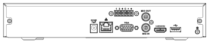
The 4K compact 1U (S2) with four PoE ports series rear panel is shown as below. See Figure 2-57.

The 4K compact 1U (S2) with eight PoE ports series rear panel is shown as below. See Figure 2-58.
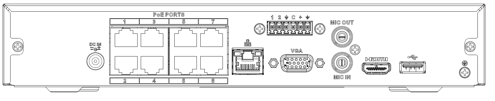
| Port Name | Connection | Function |
|---|---|---|
| USB port | USB port. Connect to mouse, USB storage device, USB burner and etc. | |
| / | Power input port | Power socket. For general 4K compact 1U (S2): DC 12V/2A power. For 4K compact 1U (S2) with four PoE ports: DC 48V/72W power. For 4K compact 1U (S2) with eight PoE ports: DC 48V/96W power. |
| Network port | 10M/100Mbps self-adaptive Ethernet port. Connect to the network cable. | |
| USB port | USB port. Connect to mouse, USB storage device and etc. | |
| HDMI | High Definition Media Interface | High definition audio and video signal output port. It transmits uncompressed high definition video and multiple-channel data to the HDMI port of the display device. HDMI version is 1.4. |
| VGA | VGA video output port | VGA video output port. Output analog video signal. It can connect to the monitor to view analog video. |
| MIC IN | Audio input port | Bidirectional talk input port. It is to receive the analog audio signal output from the devices such as microphone, pickup. |
| MIC OUT | Audio output port | Audio output port. It is to output the analog audio signal to the devices such as the sound box. Bidirectional talk output. Audio output on 1-window video monitor. Audio output on 1-window video playback. |
| GND | Ground end | |
| PoE PORTS | PoE port | Built-in switch. Support PoE function. For PoE series product, you can use this port to provide power to the network camera. |
4K 1U (S2) Series
The general 4K 1U (S2) series rear panel is shown as below. See Figure 2-59.

The 4K 1U (S2) with four PoE ports series rear panel is shown as below. See Figure 2-60.

The 4K 1U (S2) with eight PoE ports series rear panel is shown as below. See Figure 2-61.

The 4K 1U (S2) with sixteen PoE ports series rear panel is shown as below. See Figure 2-62.

| Name | Function |
|---|---|
| Power switch | Power on/off button. |
| Power input port | Input DC 12V/4A. For general 4K 1U (S2) series product only. Switch power port. Input DC 48/96W. For 4K 1U (S2) with four PoE ports series product only. Input AC90V~264V-12V5A/52V2.5A-190W. For 4K 1U (S2) with eight PoE ports/ 4K 1U (S2) with sixteen PoE ports series product only. |
| MIC IN — Audio input port | Bidirectional talk input port. It is to receive the analog audio signal output from the devices such as microphone, pickup. |
| MIC OUT — Audio output port | Audio output port. It is to output the analog audio signal to the devices such as the sound box. Bidirectional talk output. Audio output on 1-window video monitor. Audio output on 1-window video playback. |
| 1~4 — Alarm input port 1~4 | There are two types; NO (normal open)/NC (normal close). When your alarm input device is using external power, please make sure the device and the NVR have the same ground. |
| GND | Alarm input ground port. |
| N1, N2 / C1, C2 — Alarm output port 1~2 | 2 groups of alarm output ports. (Group 1:port NO1~C1, Group 2: port NO2~C2). Output alarm signal to the alarm device. Please make sure there is power to the external alarm device. NO:Normal open alarm output port. C:Alarm output public end. |
| A — RS-485 communication port | RS485_A port. It is the cable A. You can connect to the control devices such as speed dome PTZ. |
| B — RS-485 communication port | RS485_B. It is the cable B. You can connect to the control devices such as speed dome PTZ. |
| Network port | 10M/100M/1000Mbps self-adaptive Ethernet port. Connect to the network cable. |
| USB port | USB port. Connect to mouse, USB storage device, USB burner and etc. |
| RS-232 — RS-232 debug COM. | It is for general COM debug to configure IP address or transfer transparent COM data. |
| HDMI — High Definition Media Interface | High definition audio and video signal output port. It transmits uncompressed high definition video and multiple-channel data to the HDMI port of the display device. HDMI version is 1.4. |
| VGA — VGA video output port | VGA video output port. Output analog video signal. It can connect to the monitor to view analog video. |
| PoE PORTS | Built-in Switch. Support PoE. For PoE series product, you can use this port to provide power to the network camera. |
4K 1.5U (S2) Series
The general 4K 1.5U (S2) series rear panel is shown as below. See Figure 2-63.

The 4K 1.5U (S2) with sixteen PoE ports series rear panel is shown as below. See Figure 2-64.

| Name | Function |
|---|---|
| Power switch | Power on-off button |
| Power input port | AC90V~264V-12V12.5A/-53V2.83A |
| MIC IN — Audio input port | Bidirectional talk input port. It is to receive the analog audio signal output from the devices such as microphone, pickup. |
| MIC OUT — Audio output port | Audio output port. It is to output the analog audio signal to the devices such as the sound box. Bidirectional talk output. Audio output on 1-window video monitor. Audio output on 1-window video playback. |
| VIDEO OUT — Video output port | CVBS output |
| 1~16 — Alarm input port 1~16 | There are four groups. The first group is from port 1 to port 4, the second group is from port 5 to port 8, the third group is from 9 to 12, and the fourth group is from 13 to 16. They are to receive the signal from the external alarm source. There are two types; NO (normal open)/NC (normal close). When your alarm input device is using external power, please make sure the device and the NVR have the same ground. |
| Video output port | CVBS output |
| NO1~NO5 / C1~C5 / NC5 — Alarm output port 1~5 | 5 groups of alarm output ports. (Group 1:port NO1~C1, Group 2: port NO2~C2, Group 3: port NO3~C3, Group 4:port NO4~C4, Group 5: port NO5, C5, NC5). Output alarm signal to the alarm device. Please make sure there is power to the external alarm device. NO: Normal open alarm output port. C: Alarm output public end. NC: Normal close alarm output port. |
| A — RS-485 communication port | RS485_A port. It is the cable A. You can connect to the control devices such as speed dome PTZ. |
| B — RS-485 communication port | RS485_B. It is the cable B. You can connect to the control devices such as speed dome PTZ. |
| CTRL 12V | Controller 12V power output. It is to control the on-off alarm relay output. It can be used to control the device alarm output. At the same time, it can also be used as the power input source of some devices such as the alarm detector. |
| +12V | +12V power output port. It can provide the power to some peripheral devices such as the camera or the alarm device. Please note the supplying power shall be below 1A. |
| Network port | 10M/100M/1000Mbps self-adaptive Ethernet port. Connect to the network cable. |
| eSATA — eSATA port | External SATA port. It can connect to the device of the SATA port. Please jump the HDD when there is peripheral connected HDD. |
| USB2.0 port | USB2.0 port. Connect to mouse, USB storage device, USB burner and etc. |
| RS-232 — RS232 debug COM. | It is for general COM debug to configure IP address or transfer transparent COM data. |
| HDMI — High Definition Media Interface | High definition audio and video signal output port. It transmits uncompressed high definition video and multiple-channel data to the HDMI port of the display device. HDMI version is 1.3 |
| VGA — VGA video output port | VGA video output port. Output analog video signal. It can connect to the monitor to view analog video. |
| PoE PORTS — PoE port | Built-in Switch. Support PoE. For PoE series product, you can use this port to provide power to the network camera. |
Beneficio 2U / Beneficio 2U with 16 PoE ports Series
The beneficio 2U series NVR rear panel is shown as below. See Figure 2-65.
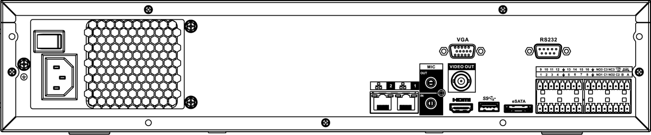
The beneficio 2U with 16 PoE ports series NVR rear panel is shown as below. See Figure 2-66.
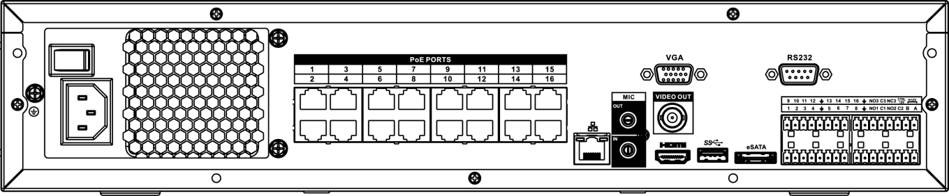
| Name | Function |
|---|---|
| Power switch | Power on-off button |
| Power input port | Input AC 100~240V. |
| MIC IN — Audio input port | Bidirectional talk input port. It is to receive the analog audio signal output from the devices such as microphone, pickup. |
| MIC OUT — Audio output port | Audio output port. It is to output the analog audio signal to the devices such as the sound box. Bidirectional talk output. Audio output on 1-window video monitor. Audio output on 1-window video playback. |
| VIDEO OUT — Video output port | CVBS output. |
| 1~16 — Alarm input port 1~16 | There are four groups. The first group is from port 1 to port 4, the second group is from port 5 to port 8, the third group is from 9 to 12, and the fourth group is from 13 to 16. They are to receive the signal from the external alarm source. There are two types; NO (normal open)/NC (normal close). When your alarm input device is using external power, please make sure the device and the NVR have the same ground. |
| GND | Alarm input ground port. |
| NO1~NO5 / C1~C5 / NC5 — Alarm output port 1~5 | 5 groups of alarm output ports. (Group 1:port NO1~C1, Group 2: port NO2~C2, Group 3: port NO3~C3, Group 4:port NO4~C4, Group 5: port NO5, C5, NC5). Output alarm signal to the alarm device. Please make sure there is power to the external alarm device. NO: Normal open alarm output port. C: Alarm output public end. NC: Normal close alarm output port. |
| A — RS-485 communication port | RS485_A port. It is the cable A. You can connect to the control devices such as speed dome PTZ. |
| B — RS-485 communication port | RS485_B. It is the cable B. You can connect to the control devices such as speed dome PTZ. |
| CTRL 12V | Controller 12V power output. It is to control the on-off alarm relay output. It can be used to control the device alarm output. At the same time, it can also be used as the power input source of some devices such as the alarm detector. |
| +12V | +12V power output port. It can provide the power to some peripheral devices such as the camera or the alarm device. Please note the supplying power shall be below 1A. |
| Network port | One 10M/100M/1000Mbps self-adaptive Ethernet port. Connect to the network cable. |
| eSATA — eSATA port | External SATA port. It can connect to the device of the SATA port. Please jump the HDD when there is peripheral connected HDD. |
| USB2.0 port | USB2.0 port. Connect to mouse, USB storage device, USB burner and etc. |
| RS-232 — RS-232 debug COM. | It is for general COM debug to configure IP address or transfer transparent COM data. |
| HDMI — High Definition Media Interface | High definition audio and video signal output port. It transmits uncompressed high definition video and multiple-channel data to the HDMI port of the display device. HDMI version is 1.3 |
| VGA — VGA video output port | VGA video output port. Output analog video signal. It can connect to the monitor to view analog video. |
| PoE PORTS — 16 PoE ports | Built-in Switch. Support PoE. The 16 PoE ports series products supports total 150W power. One PoE port max supports 15W. |
4K 2U (S2) Series
The general 4K 2U (S2) series rear panel is shown as below. See Figure 2-67.

The 4K 2U (S2) with sixteen PoE ports series rear panel is shown as below. See Figure 2-68.

| Name | Function |
|---|---|
| Power switch | Power on-off button |
| Power input port | AC90V~264V-12V12.5A/-53V2.83A |
| MIC IN — Audio input port | Bidirectional talk input port. It is to receive the analog audio signal output from the devices such as microphone, pickup. |
| MIC OUT — Audio output port | Audio output port. It is to output the analog audio signal to the devices such as the sound box. Bidirectional talk output. Audio output on 1-window video monitor. Audio output on 1-window video playback. |
| VIDEO OUT — Video output port | CVBS output. |
| 1~16 — Alarm input port 1~16 | There are four groups. The first group is from port 1 to port 4, the second group is from port 5 to port 8, the third group is from 9 to 12, and the fourth group is from 13 to 16. They are to receive the signal from the external alarm source. There are two types; NO (normal open)/NC (normal close). When your alarm input device is using external power, please make sure the device and the NVR have the same ground. |
| GND | Alarm input ground port. |
| NO1~NO5 / C1~C5 / NC5 — Alarm output port 1~5 | 5 groups of alarm output ports. (Group 1:port NO1~C1, Group 2: port NO2~C2, Group 3: port NO3~C3, Group 4:port NO4~C4, Group 5: port NO5, C5, NC5). Output alarm signal to the alarm device. Please make sure there is power to the external alarm device. NO: Normal open alarm output port. C: Alarm output public end. NC: Normal close alarm output port. |
| A — RS-485 communication port | RS485_A port. It is the cable A. You can connect to the control devices such as speed dome PTZ. |
| B — RS-485 communication port | RS485_B. It is the cable B. You can connect to the control devices such as speed dome PTZ. |
| CTRL 12V | Controller 12V power output. It is to control the on-off alarm relay output. It can be used to control the device alarm output. At the same time, it can also be used as the power input source of some devices such as the alarm detector. |
| +12V | +12V power output port. It can provide the power to some peripheral devices such as the camera or the alarm device. Please note the supplying power shall be below 1A. |
| Network port | One 10M/100M/1000Mbps self-adaptive Ethernet port. Connect to the network cable. |
| eSATA — eSATA port | External SATA port. It can connect to the device of the SATA port. Please jump the HDD when there is peripheral connected HDD. |
| USB port | USB port. Connect to mouse, USB storage device, USB burner and etc. |
| RS-232 — RS-232 debug COM. | It is for general COM debug to configure IP address or transfer transparent COM data. |
| HDMI — High Definition Media Interface | High definition audio and video signal output port. It transmits uncompressed high definition video and multiple-channel data to the HDMI port of the display device. HDMI version is 1.4. |
| VGA — VGA video output port | VGA video output port. Output analog video signal. It can connect to the monitor to view analog video. |
| PoE PORTS — PoE port | Built-in Switch. Support PoE. For PoE series product, you can use this port to provide power to the network camera. |
Smart 1U 4K (S2) with Wireless Series
The rear panel is shown as below. See Figure 2-69.
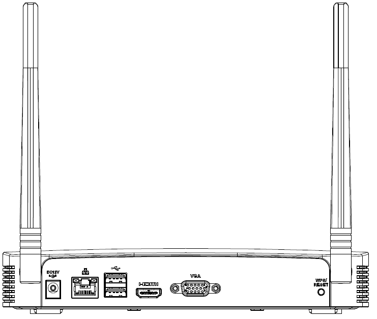
| Port Name | Connection | Function |
|---|---|---|
| USB2.0 port | USB2.0 port. Connect to mouse, USB storage device, USB burner and etc. | |
| Network port | 10M/100Mbps self-adaptive Ethernet port. Connect to the network cable. | |
| HDMI | High Definition Media Interface | High definition audio and video signal output port. It transmits uncompressed high definition video and multiple-channel data to the HDMI port of the display device. HDMI version is 1.4. |
| VGA | VGA video output port | VGA video output port. Output analog video signal. It can connect to the monitor to view analog video. |
| Power input port | Input DC 12V/2A. | |
| WPS/RESET | Reset/WPS function | Device Wi-Fi reset and WPS function button: Hold down this button for 5 seconds and above to restore Wi-Fi AP to defaults. Press this button for less than 2 seconds, and then press the WPS button of Wi-Fi IPC, the device and Wi-Fi IPC can be connected. |
Compact 1U 4K (S2) with Wireless Series
The rear panel is shown as below. See Figure 2-70.
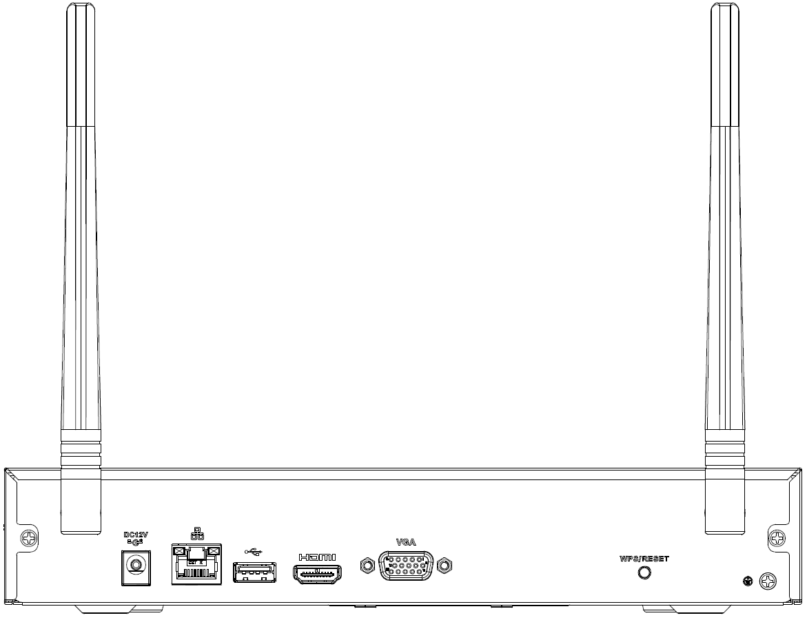
| Icon | Name | Function |
|---|---|---|
| Power input socket | Power socket. Input DC12V/2A. | |
| Network port | 10M/100Mbps self-adaptive Ethernet port. Connect to the network cable. | |
| USB2.0 port | USB2.0 port. Connect to mouse, USB storage device, and etc. | |
| HDMI | High Definition Media Interface | High definition audio and video signal output port. It transmits uncompressed high definition video and multiple-channel data to the HDMI port of the display device. HDMI version is 1.4. |
| VGA | VGA video output port | VGA video output port. Output analog video signal. It can connect to the monitor to view analog video. |
| GND | Ground end | |
| WPS/RESET | Reset/WPS function | Device Wi-Fi reset and WPS function button: Hold down this button for 5 seconds and above to restore Wi-Fi AP to defaults. Press this button for less than 2 seconds, and then press the WPS button of Wi-Fi IPC, the device and Wi-Fi IPC can be connected. |
Cooper 1U (S3) / Cooper 1U (S3) with 4 PoE Ports / Compact 1U (S3) with 8 PoE Ports Series
The Cooper 1U (S3) NVR rear panel is shown as below. See Figure 2-71.
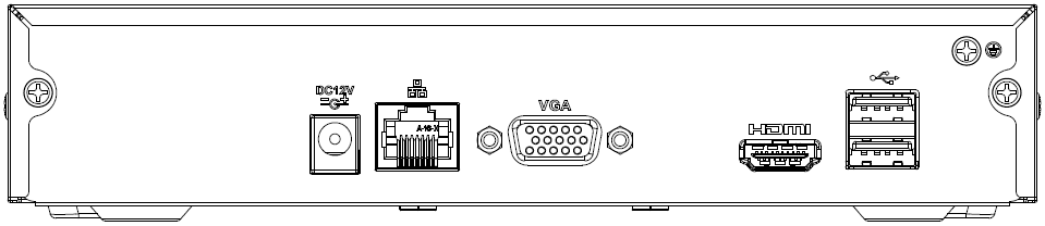
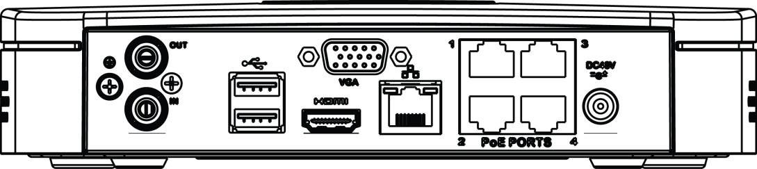
The Cooper 1U (S3) with 4 PoE Ports NVR rear panel is shown as below. See Figure 2-72.
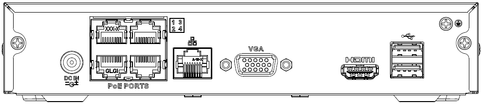
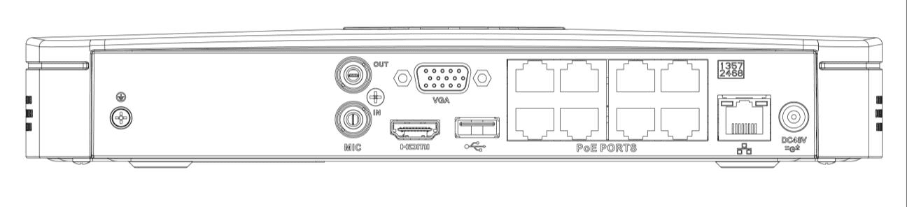
The Compact 1U (S3) with 8 PoE Ports NVR rear panel is shown as below. See Figure 2-73.
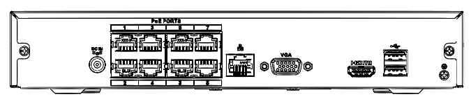
| Port Name | Connection | Function |
|---|---|---|
| Power input port | Power socket. | |
| PoE PORTS | PoE port | Built-in switch. Support PoE function. For PoE series product, you can use this port to provide power to the network camera. |
| Network port | 10M/100Mbps self-adaptive Ethernet port. Connect to the network cable. | |
| VGA | VGA video output port | VGA video output port. Output analog video signal. It can connect to the monitor to view analog video. |
| MIC IN | Audio input port | Bidirectional talk input port. It is to receive the analog audio signal output from the devices such as microphone, pickup. |
| MIC OUT | Audio output port | Audio output port. It is to output the analog audio signal to the devices such as the sound box. Bidirectional talk output. Audio output on 1-window video monitor. Audio output on 1-window video playback. |
| HDMI | High Definition Media Interface | High definition audio and video signal output port. It transmits uncompressed high definition video and multiple-channel data to the HDMI port of the display device. |
| USB port | USB port. Connect to mouse, USB storage device and etc. | |
| GND | Ground end |